Fig 2 fig 3 fig 4, Description & specification, Preparing inverter for use – Sealey TIG161HFACDC User Manual
Page 3: Fig 1, Fig 5
2.1
DESCRIPTION
Fan cooled AC/DC power supply suitable for TIG and MMA welding applications. Lightweight, compact unit with high quality technology, suitable for welding
aluminium, magnesium, stainless steel, steel, deoxidised copper, nickel and titanium. TIG cycle includes post gas and current down-slope regulation. Features
regulated HF push button arc that prevents having to touch the workpiece, keeping the tip in good condition for longer. Includes connector for foot pedal or hand
controller for when more control is required. Supplied with shoulder strap.
2. DESCRIPTION & SPECIFICATION
2.2
SPECIFICATION
Power Output: . . . . . . . . . . . . . . . . . . . . . . . . . . . . . . . . 5-160 A
Duty Cycle: . . . . . . . . . . . . . . . . . . . . . . . . . . . . . . 25% @ 130 A
Electrode Capacity: . . . . . . . . . . . . . . . . . . . . . . . Ø1.6 - 3.2mm
Maximum absorbed power: . . . . . . . . . . . . . . . . . . . . . . 4.3 KW
Mains Voltage: . . . . . . . . . . . . . . . . . . . . . . . . . . . . . . 230V -1ph
Insulation Class: . . . . . . . . . . . . . . . . . . . . . . . . . . . . . . . . . . . . H
Protection: . . . . . . . . . . . . . . . . . . . . . . . . . . . . . . . . . . . . . .IP23
Weight: . . . . . . . . . . . . . . . . . . . . . . . . . . . . . . . . . . . . . . . 9.4kg
ARC Accessory Ref:. . . . . . . . . . . . . . . . . . (optional) INVMMA2
Foot Pedal Power Control: . . . . . . . . . . . . . (optional) INV/TIG/5
Current Control: . . . . . . . . . . . . . . . . . . . . . (optional) INV/TIG/7
3. PREPARING INVERTER FOR USE
3.1
CONNECTION TO MAINS.
3.1.1
Whilst welding at low power levels is possible on a 13Amp supply the Inverter will normally be connected to a 30Amp supply in order to TIG weld at higher
power levels and in order to perform ordinary ARC welding. See section 1, item 1.1.10.
3.2
WELDING CABLE CONNECTION.
3.2.1
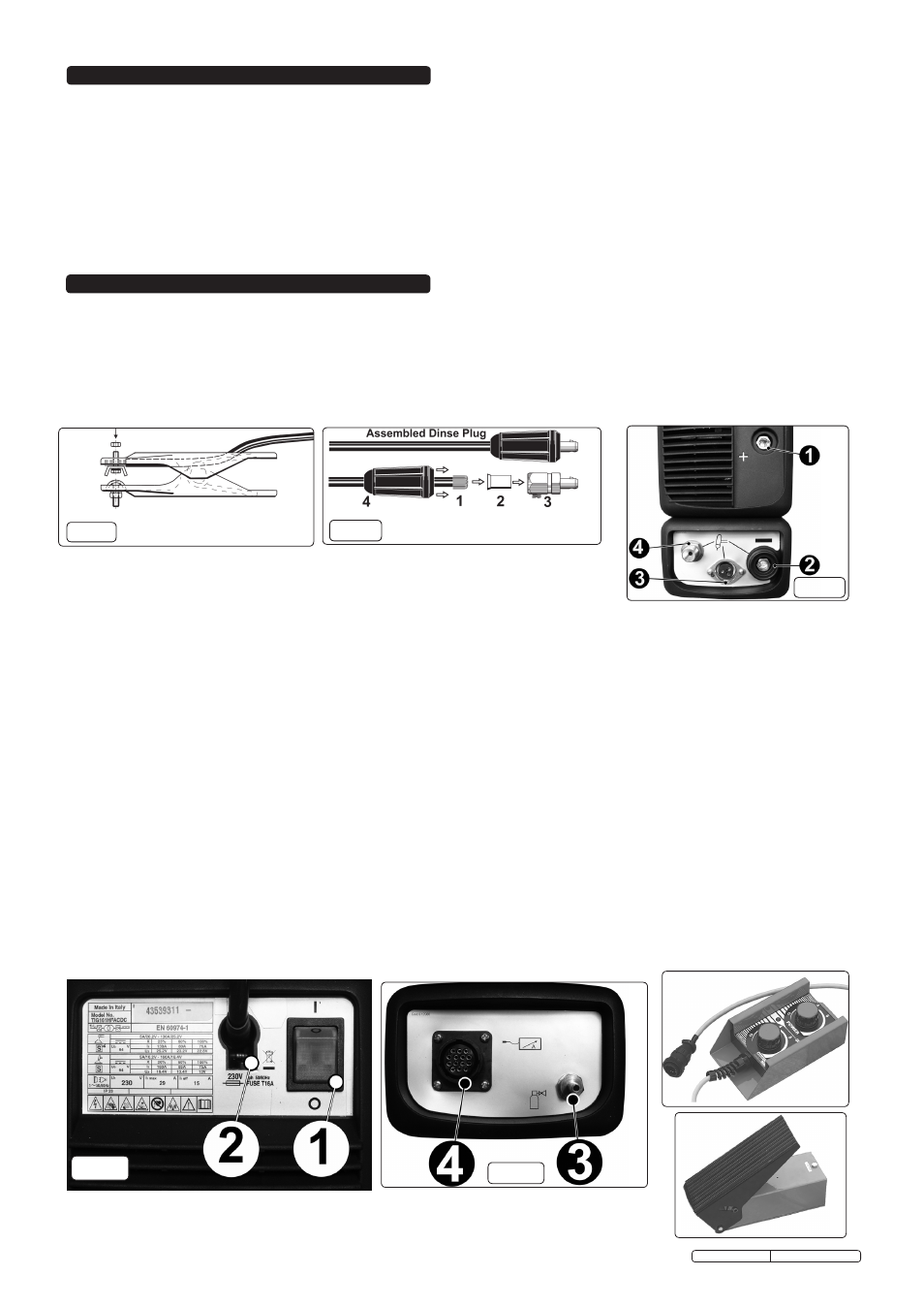
The torch cable is supplied ready assembled but it may be necessary for you to assemble the work clamp cable. Attach the work clamp to one end of the
cable as shown in fig.1. To connect the Dinse Plug as shown in fig.2 first thread the cable through the outer cover of the plug (see fig.2 item 4). Now remove
20mm of insulation sheath from the end of the cable and fold back the copper wire all around the outside of the sheath (1). Push the cable end into the
copper sleeve (2) so that the folded back wire makes good contact with the inside of the sleeve. Push the copper sleeve into the brass plug body (3) and
tighten the large grub screw until the cable is firmly held. Now slide the outer plug cover up the cable and press the brass body into it as shown in fig.2.
3.3
TIG CONNECTIONS:
3.3.1
TIG TORCH CABLE.
Dinse plug at end of the torch cable will be connected to the
negative socket (-)
on lower front panel see fig.3 item 2.
3 pin torch plug at end of torch cable will be connected to circular 3 pin socket on the lower front panel (see fig.3 item 3).
Black gas pipe with brass fitting at end of torch cable will be screwed to brass fitting on lower front panel (see fig.3 item 4).
3.3.2
WORK CLAMP CABLE. Dinse plug at end of the clamp cable will be connected to the positive socket (+) on lower front panel (see fig.3 item 1).
(*) Please note that the way the welding cables are connected to the inverter for ordinary ARC welding may be different to the way the cables are
connected for standard TIG welding. Whilst most stick electrodes are connected to the positive terminal certain types need to be connected to the
negative terminal. It is therefore essential that the user refers to the manufacturer’s instructions for the electrodes to ensure that the correct
polarity is selected.
3.4
ARC CONNECTIONS
(You will need optional ARC Accessory Kit INVMMA2).
ELECTRODE HOLDER Plug at the end of electrode cable will normally (*) be connected to the positive socket (+) on the front panel (see fig.3 item 1).
WORK CLAMP CABLE. Plug at the end of the clamp cable will normally (*) be connected to the negative socket (-) on the front panel (see fig.3 item 2).
3.5
REAR PANEL LAYOUT (refer to Figs 4 & 5).
1. ON/OFF SWITCH: O = Off, I = On.
2. MAINS CABLE
3. GAS INLET FITTING. For connecting the gas cylinder to the welder using clear tubing provided.
4. REMOTE CONTROL CONNECTOR. For the connection of the optional remote controls shown below.
3.6
REMOTE CONTROLS. (Optional) Two types of remote control can be connected to the machine via the 14 pin connector situated on the back panel (See
fig.5 item 4). The device will be automatically recognised. The encoder knob on the main control panel will become inoperative for those functions taken over
by the remote control.
3.6.1
Remote control pedal. (Model No. INV/TIG/5) When activated the pedal will control the main welding current. Also in 2-stroke TIG welding mode the first
movement of the pedal will initiate the striking of the arc in place of the torch button.
3.6.2
Remote control with two potentiometers. (Model No. INV/TIG/7) The knob furthest away from the cable entry, controls the main welding current. The
second knob will control one other parameter depending on the active welding mode. The rotation of the second knob automatically selects the appropriate
parameter and brings it up on the display.
3.6.3
Welding mode set up.
Parameter for second Knob.
MMA welding with stick electrode. . . . . . . . . . . . . ARC FORCE (Not displayed)
TIG DC, HF or LIFT, 2 or 4 stroke, . . . . . . . . . . . . . . . . . . . . . . . . . .POST GAS
TIG AC , 2 or 4 stroke . . . . . . . . . . . . . . . . . . . . . . . . . . . . . . . . . . . .POST GAS
fig 1
fig 2
fig 3
fig 4
Original Language Version
TIG161HFACDC Issue: 1 - 03/11/11
fig 5