Electromagnetic compatibility, Troubleshooting – Sealey TIG161HFACDC User Manual
Page 8
Original Language Version
TIG161HFACDC Issue: 1 - 03/11/11
10. ELECTROMAGNETIC COMPATIBILITY
THIS EQUIPMENT IS IN CONFORMITY WITH THE EUROPEAN STANDARD EN 50199 : - ELECTROMAGNETIC COMPATIBILITY OF ARC WELDING
EQUIPMENT AND SIMILAR PROCESSES (e.g. MMA AND PLASMA CUTTING )
10.1 PROTECTION AGAINST INTERFERENCE. (E.M.C.) The emission limits in this standard may not, however, provide full protection against interference to
radio and television reception when the welding equipment is used closer than 30m to the receiving antenna. In special cases, when highly susceptible
apparatus is being used in close proximity, additional mitigation measures may have to be employed in order to reduce the electromagnetic emissions. At
the same time there could occur some potential difficulties in having electromagnetic compatibility in a non-industrial environment (e.g. in residential areas).
Therefore it is most important that the welding equipment is used and installed according to the following instructions.
10.2 INSTALLATION AND USE. The user is responsible for installing and using the welding equipment according to these instructions. If electromagnetic
disturbances are detected, then it shall be the responsabillity of the user of the welding equipment to resolve the situation with the technical assistance of
the supplier. In some cases this remedial action may be as simple as earthing the circuit (see Note *). In other cases it could involve constructing an
electromagnetic screen enclosing the welding power source and the work complete with associated input filters. In all cases the electromagnetic
disturbances shall be reduced to the point where they are no longer troublesome.
Note * : The welding circuit may or may not be earthed for safety reasons. Changing the earthing arrangements should only be authorised by a person who
is competent to assess whether the changes will increase the risk of injury, e.g. by allowing parallel welding circuit return paths which may damage the
earth circuits of other equipment. Further guidance is given in IEC 974-13,’Arc welding equipment - Installation and use.’ (Under preparation)
10.3 ASSESSMENT OF AREA. Before installing welding equipment the user shall make an assessment of potential electromechanical problems in the
surrounding area. The following shall be taken into account:
a) Other supply cables, control cables, signalling and telephone cables, above, below and adjacent to the welding equipment.
b) Radio and television transmitters and receivers.
c) Computer and other control equipment.
d) Safety critical equipment,e.g. Security monitoring of industrial equipment.
e) The health of people in the vicinity, e.g. Persons fitted with a pacemaker or hearing aid.
f) Equipment used for calibration or measurement.
g) The immunity of other equipment in the environment. The user shall ensure that other equipment being used in the environment is compatible. This may
require additional protective measures.
h) The time of day that welding and other activities are to be carried out.
NOTE: The size of the surrounding area to be considered will depend on the structure of the building and other activities that are taking place. The
surrounding area may extend beyond the boundaries of the premises.
10.4 MAINS SUPPLY. The Inverter should be connected to the mains supply according to these instructions. If interference occurs, it may be necessary to take
additional precautions such as filtering of the mains supply. Consideration should also be given to shielding the supply cable of permanently installed
welding equipment, in metallic conduit or equivalent. This shielding should be connected to the welding power source so that good electrical contact is
maintained between the conduit and the welding power source enclosure.
10.5 MAINTENANCE OF THE WELDING EQUIPMENT. The welding equipment should be routinely maintained according to these instructions. All access and
service door covers should be closed and properly fastened when the welding equipment is in operation. The welding equipment should not be modified in
any way except for those changes and adjustments covered in these instructions. In particular, the spark gaps of arc striking and stabilising devices should
be adjusted and maintained according to these instructions
10.6 WELDING CABLES. The welding cables should be kept as short as possible and should be positioned close together, running at or close to the floor level.
10.7 EQUIPOTENTIAL BONDING. Bonding of all metallic components in the welding installation and adjacent to it should be considered. However, metallic
components bonded to the workpiece will increase the risk that the operator could receive a shock by touching these metallic components and the
electrode at the same time. The operator should be insulated from all such bonded metallic components.
10.8 EARTHING OF THE WORKPIECE. Where the workpiece is not bonded to earth for electrical safety, nor connected to earth because of its size and
position, e.g. ship’s hull or building steelwork, a connection bonding the workpiece to earth may reduce emissions in some, but not all instances. Care
should be taken to prevent the earthing of the workpiece increasing the risk of injury to others or damage to other electrical equipment. Where necessary,
the connection of the workpiece to earth should be made by a direct connection to the workpiece, but in some countries where direct connection is not
permitted, the bonding should be achieved by a suitable capacitance, selected according to national regulations.
10.9 SCREENING AND SHIELDING. Selective screening and shielding of other cables and equipment in the surrounding area may alleviate problems of
interference. Screening of the entire welding installation may be considered for special applications.
9. TROUBLESHOOTING
9.1
TIG WELDING
9.1.1
Yellow fault indicator is illuminated. When this LED illuminates the machine will be ‘blocked’ and one of three alarm conditions will appear on the display.
“AL 1”
Failure in the primary power supply. If the supply voltage drops below 190V AC or rises above 260V AC the machine is turned off.
Reconnect the inverter to a more stable supply of 230V AC. (Mains voltages over 280V AC will damage the inverter).
Short circuit has occurred. If a short circuit has occurred lasting more than 1.5 seconds (e.g. during the striking of the arc) the inverter is
switched off. In this case, wait for the inverter to restart automatically.
“AL 2”
Inverter has overheated. One of the safety thermostats has triggered due to the machine overheating. Leave the machine to cool to normal
temperature at which point it will reset itself automatically. Do not restart the inverter until the reason for overheating has been understood and
resolved. (see below)
9.1.2
Overheating. This may occur for one of the following reasons:
a) Inverter casing is full of dust making cooling system inefficient. Clean as described in section 8.1.
b) Fan not working. Have fan renewed by authorised service agent.
c) Electrode does not match the collet and collet body fitted within the torch. Obtain and fit the correct size of torch components for the electrode selected.
d) Bad connection in welding cable and/or work clamp has made poor connection with workpiece. Check and clean all connections..
9.1.3
Poor weld quality.
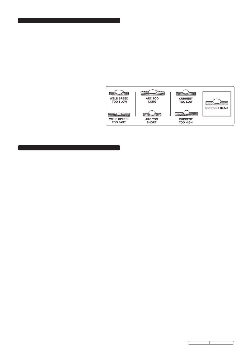
a) Refer to arc weld bead diagrams to the right and also to AC welding parameters in fig.10.
b) Check condition of electrode. It should be ground to the correct shape as seen in fig.7 and should be symmetrically conical.
c) Check that correct gas flow is being used.
d) Check that correct ceramic nozzle is fitted to torch.
9.1.4
Difficulty in striking an arc.
This is usually due to the electrode not being in good
condition. Grind to correct shape or replace.
9.1.5
Incompatible settings. In some instances the machine
will not work due to the fact that a combination of
settings has been chosen that are electrically
incompatible. In such instances no damage can be
caused to the machine but it will be necessary to review
and alter the settings to a more appropriate combination.
9.2
MMA WELDING
9.2.1
Burning through thin metal: On very thin sheet, e.g. car body work, the lowest amperage setting may be too fierce. In this case revert to TIG welding.
9.2.2
Machine cuts out: Refer to fault indicator information above.
9.2.3
Difficulty in striking an arc:
a). The electrode is damp. Heat it up to 60º - 70º before using.
b). Wrong type of rod.