Fig 7, Fig 6 fig 8, Fig 9 – Sealey TIG161HFACDC User Manual
Page 4: Control panel
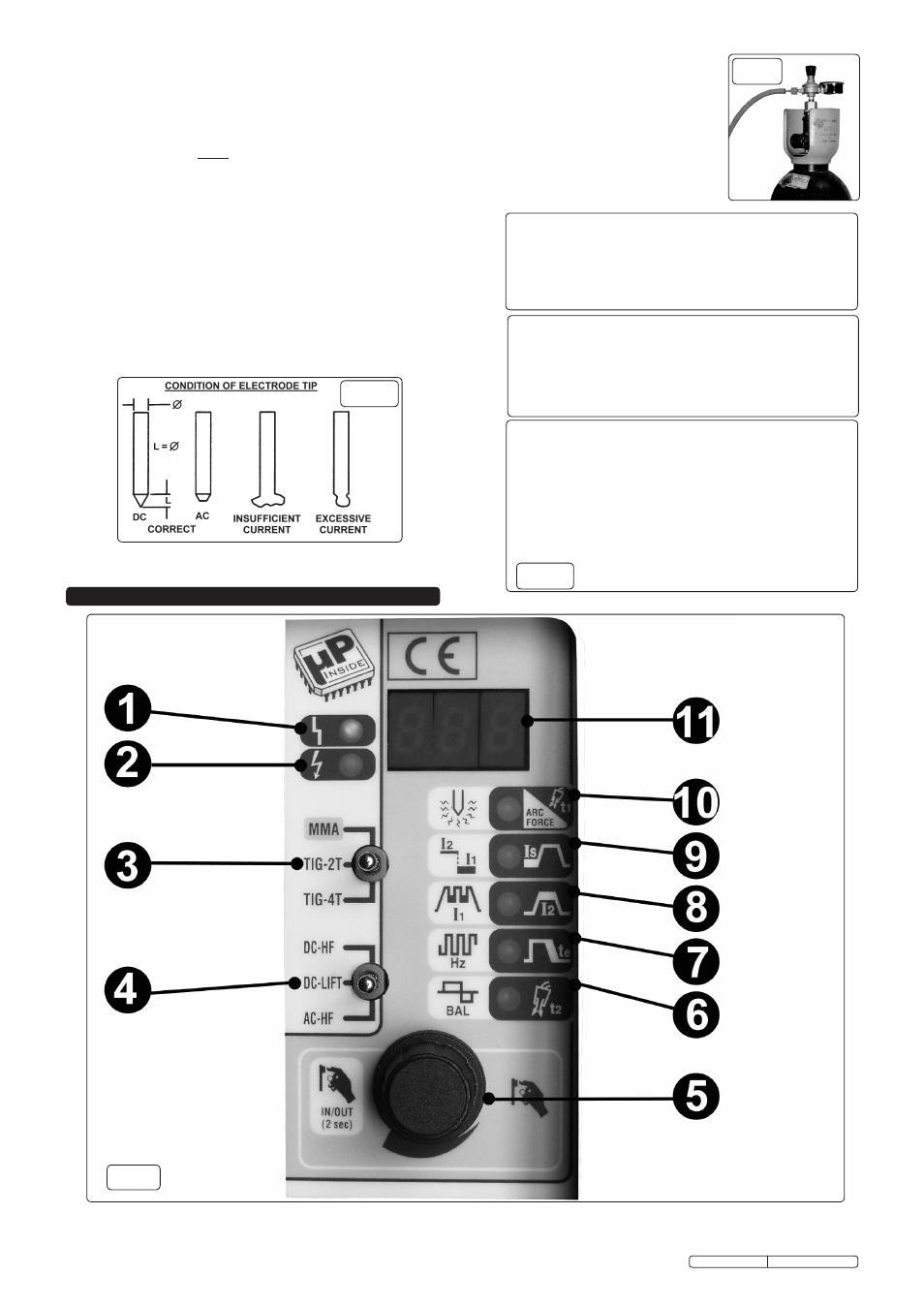
4. CONTROL PANEL
3.8
PREPARATION AND CHOICE OF ELECTRODE. In order to produce a good
weld it is important to choose an electrode of the correct diameter for the current
to be used. For a general guide to the settings to be used with particular
diameters of electrodes please refer to the adjacent tables. The electrode will
normally protrude from the ceramic nozzle by 2 to 3mm but in order to gain
access to inaccessible areas such as internal corners the electrode can be made
to protrude by up to 8mm. The chosen electrode should be sharpened axially on
a grinding wheel as indicated in the diagram below. The tip should be
perfectly concentric in order to avoid arc deviations. The condition of the
electrode should be regularly inspected to maintain it in peak condition.
3.9
PREPARATION OF THE WORKPIECE. For a good weld it is important that the
workpiece is thoroughly cleaned so that no oxides, oil, grease or solvents remain
on the surface of the material.
fig 7
TIG WELDING PARAMETERS FOR STAINLESS STEEL (DC)
Thickness Current Electrode
Nozzle
Argon Filler Rod
(mm)
( A )
(diam mm) (diam mm) ( L/min ) (diam mm)
0.3 - 0.5
5 - 20
0.5
6.5
3
---
0.5 - 0.8
15 - 30
1
6.5
3
---
1
30 - 60
1
6.5
3 - 4
1
1.5
70 -100
1.6
9.5
3 - 4
1.5
2
90 - 110
1.6
9.5
4
1.5 - 2.0
3
120 - 150
2.4
9.5
6
2 - 3
4
140 - 190
2.4
9.5 - 11
5 - 6
3.0
TIG WELDING PARAMETERS FOR DEOXIDATED COPPER (DC)
Thickness Current Electrode
Nozzle
Argon Filler Rod
(mm)
( A )
(diam mm) (diam mm) ( L/min ) (diam mm)
0.3 - 0.8
15 - 60
0.5 - 1
6.5
4
---
1
50 - 100
1.0
9.5
6
1.5
1.5
30 - 60
1.6
9.5
8
1.5
2.0
70 - 100
1.6
9.5
8
1.5
TIG WELDING PARAMETERS FOR ALUMINIUM (AC)
Thickness Current Electrode
Nozzle
Argon Filler Rod
(mm)
( A )
(diam mm) (diam mm) ( L/min ) (diam mm)
1
30 - 40
1 - 1.6
6.5
4 - 6
1.2 - 2
1.5
60 - 85
1.6
9.5
4 - 6
2
2
70 - 90
1.6
9.5
4 - 6
2
3
110 - 160
2.4
11
5 - 6
2
3.7 CONNECTING THE GAS
3.7.1 When using Argon gas fit the Bull Nose Adaptor supplied, to the cylinder with a spanner.
3.7.2. Fit the gas regulator onto the Bull Nose Adaptor (see fig.6).
3.7.3 Using the clear tubing supplied connect the regulator to the gas inlet on the back of the inverter (see fig.5a - 3). Hold the
tubing securely in place on each connector by using the worm drive clamps supplied.
3.7.4 Open the regulator before opening the cylinder valve. Test for leaks.
3.7.5. Set the gas flow to suit the welding parameters required. See WELDING PARAMETER TABLES below for general guidance.
3.7.6 If necessary the gas flow can be adjusted during welding using the regulator knob.
fig 6
fig 8
Original Language Version
TIG161HFACDC Issue: 1 - 03/11/11
fig 9