Circuit schematic, Ratings plate symbols – Sealey TIG161HFACDC User Manual
Page 9
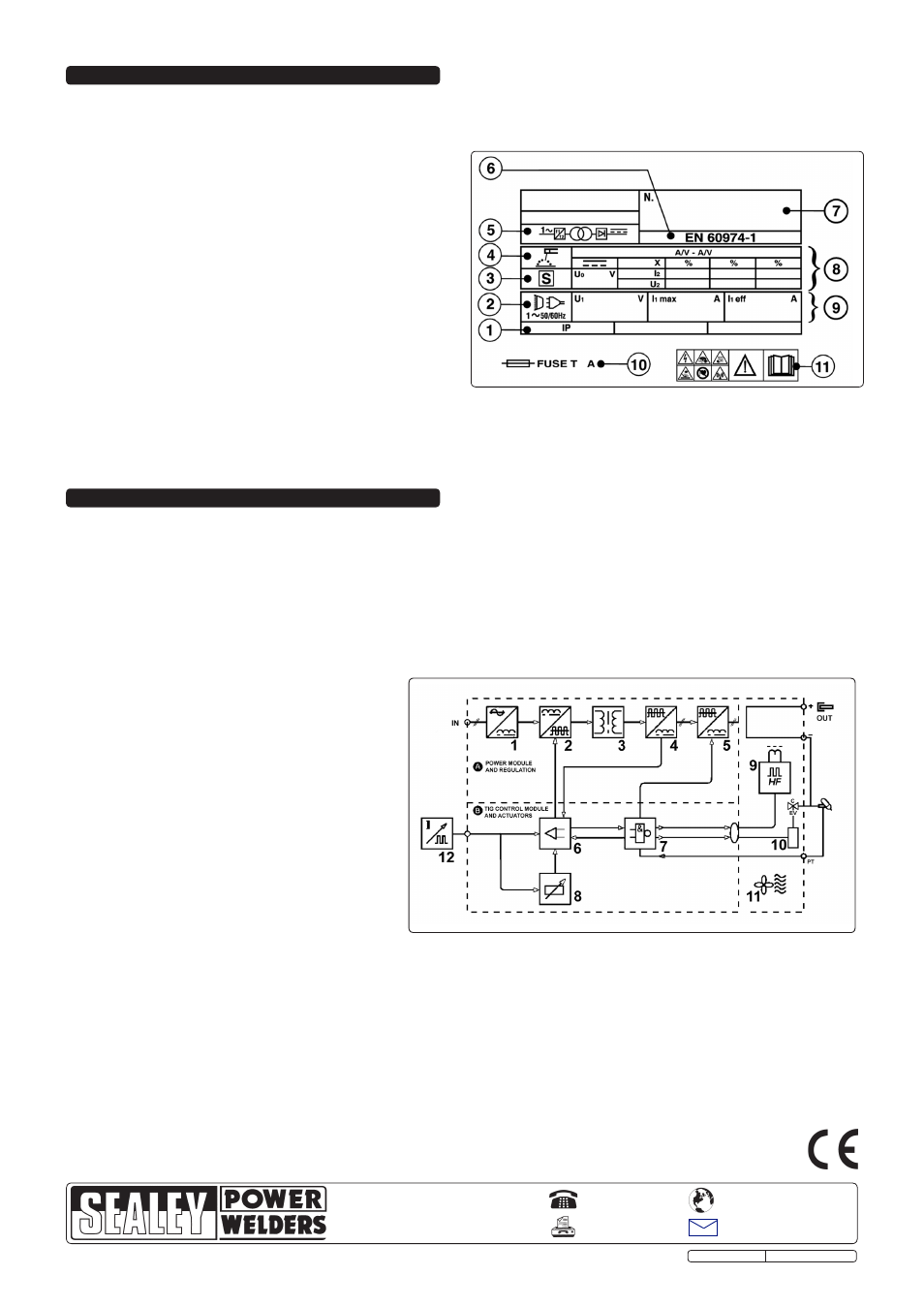
1.
Mains input (single phase), rectifier unit and condenser.
2.
Transistors and drivers switching bridge (IGBT). Turns the mains rectified voltage into high frequency alternating voltage (60khz) and permits power
regulation according to the current/voltage of weld to be done.
3.
High frequency transformer: The primary windings are fed by the voltage converted by Block 2, it has the function of adapting voltage and current to values
required by the ARC welding procedure and, simultaneously, isolates the welding circuit from mains.
4.
Secondary rectifier bridge with inductance. Changes the alternating voltage/current supplied by secondary windings into continuous current/voltage at a low
wavelength.
5.
Controlled diode bridge (SCR) and drivers. It transforms the output current to the secondary circuit from DC to AC for AC TIG welding.
6.
Regulation and control electronics. Controls instantly the value of welding current transistors and compares it with the value set by the operator and
modulates the drive impulses of the IGTSs’ drivers which execute the regulation.
7.
Machine operation control logic. Sets up the welding cycles, controls the actuators and monitors the safety systems.
8.
Display, parameter setting and running modes panel.
9.
HF striking generator.
10.
Electrovalve for gas protection.
11.
Machine intelligent cooling fan.
12. Remote regulation.
12. CIRCUIT SCHEMATIC
01284 757500
01284 703534
Sole UK Distributor, Sealey Group,
Kempson Way, Suffolk Business Park
,
Bury St. Edmunds, Suffolk,
IP32 7AR
www.sealey.co.uk
Web
TIG161HFACDC Issue: 1 - 03/11/11
Original Language Version
NOTE: It is our policy to continually improve products and as such we reserve the right to alter data, specifications and component parts without prior notice.
IMPORTANT: No liability is accepted for incorrect use of this product.
WARRANTY: Guarantee is 12 months from purchase date, proof of which will be required for any claim.
INFORMATION: For a copy of our latest catalogue and promotions call us on 01284 757525 and leave your full name and address, including postcode.
11. RATINGS PLATE SYMBOLS
Detailed technical data relative to the performance of the machine is located on the back panel plate.
Please note that the ratings plate shown below is an
example only intended to assist with the explanations of symbols. To determine the correct technical values of the machine in your possession, you must
refer to the data plate.
On the rear of the inverter is the ratings plate, giving the following data:
1 - Rating of internal protection provided by casing.
2 - Symbol for power supply line: 1= Single-phase AC.
3 -
S: Indicates that welding may be carried out in environments with a
heightened risk of electric shock e.g. very close to large metallic objects.
4 - Welding procedure: manual arc welding with covered electrode
5 - Symbol for internal structure of the welding machine.
6 - The EUROPEAN standard relating to the safety and construction
of arc welding machines.
. 7 - Manufacturers Serial Number for welding machine identification.
8 - Output
Uº: Maximum no load voltage.
I
²
, U
²
: Current and corresponding normalised voltage that the
welding machine can supply during welding.
X: Welding ratio based on a 10 minute duty cycle. 30% indicates 3
minutes welding and 7 minutes rest, 100% indicates continuous welding.
A/V-A/V: Shows the range of adjustment for the welding current
(minimum - maximum) at the corresponding arc voltage.
9 - Power Supply
U
1: Alternating voltage and power supply frequency of welding machine. (allowed limit ± 10%)
I
1 max: Maximum current absorbed by the line.
I
1 eff: Effective current supplied.
10 - Size of delayed fuse for protection of power supply.
11 - Symbols referring to safety regulations.