Fig 10, Tig welding procedure – Sealey TIG161HFACDC User Manual
Page 6
Original Language Version
TIG161HFACDC Issue: 1 - 03/11/11
5.4
TIG DC WELDING.
5.4.1 TIG DC welding is suitable for all low and high carbon steels and the heavy metals, copper, nickel, titanium and their alloys.
5.4.2 For TIG DC welding with the electrode to the negative (-) terminal an electrode with 2% thorium (red band) is usually used or alternatively an electrode with
cerium (grey band).
5.4.3 It is necessary to sharpen the Tungsten electrode axially on a grinding wheel as shown in fig.7, making sure that the tip is perfectly concentric to prevent arc
deviation. This procedure should be repeated periodically, depending on the amount of use and wear of the electrode or when the electrode has been
contaminated, oxidised or used incorrectly.
5.4.4 In TIG DC mode both 2-stroke (2T) and 4-stroke (4T) operations are possible.
5.5
TIG AC WELDING.
5.5.1 This type of welding can be used to weld metals such as aluminium and magnesium, which form a protective, insulating oxide on their surface. By reversing
the welding current polarity it is possible to 'break' the surface layer of oxide by means of a mechanism called 'ionic sandblasting'. The voltage on the
electrode alternates between positive (EP) and negative (EN). During the EP period the oxide is removed from the surface ('cleaning' or 'pickling') allowing
the formation of the pool. During the EN period there is a massive heat transfer to the piece, allowing welding. The possibility of varying the balance
parameter in AC means that it is possible to reduce the EP current period to a minimum, allowing quicker welding.
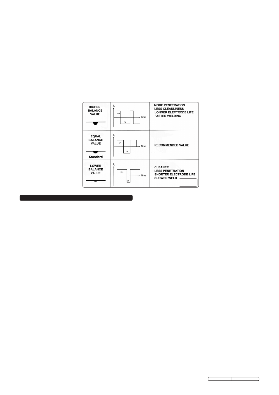
5.5.2 Higher balance values give quicker welding, greater penetration, a more concentrated arc, a narrower weld pool and limited heating of the electrode. Lower
values give a cleaner piece. If the balance value is too low this will widen the arc and the de-oxidised part, overheat the electrode with the consequent
formation of a sphere on the tip making it difficult to strike the arc and control its direction. If the balance value is too high this will create a 'dirty' weld pool
with dark inclusions (fig.10).
5.5.3 In TIG AC mode both 2-stroke (2T) and 4-stroke (4T) operations are possible.
6. TIG WELDING PROCEDURE
WARNING: use welding head shield to protect eyes and avoid exposing skin to ultraviolet rays given off by electric arc. Wear safety welding gauntlets.
If difficult welds are to be performed and the welding parameters are unknown, it is advisable to carry out several trial runs on test pieces in order to
determine the right welding current and gas flow.
SWITCH ON the welder only when you are satisfied that the welder is correctly connected and the work to be done is fully prepared.
6.1
SETTING THE CONTROLS. (Select the welding mode and adjust the appropriate parameters for the intended welding task)
6.1.1 Regulate the welding current to the required value through the BUTTON AND ENCODER. It may be necessary to make further adjustments during welding.
6.1.2 Press the torch pushbutton to verify the correct gas outflow from the torch. Adjust the PRE GAS and POST GAS timings to suit the welding operation. In
particular, the gas delay must be such as to permit the cooling off of the electrode and the weld pool without them coming into contact with the atmosphere
(oxidisations and contaminations) at the end of welding.
6.2
STRIKING THE ARC. (HF facility) Press and hold the torch button bringing the electrode tip to within 2 - 3mm of the workpiece. The arc will be struck by
high frequency impulses. When the arc is established, form a molten pool on the workpiece, introduce the filler rod and proceed along the joint. When the
arc is difficult to strike, despite the presence of gas and visible high frequency discharges it is not advisable to carry on for any length of time. Before
continuing, check the integrity of the electrode surface and tip and if necessary regrind the tip.
6.3
STRIKING THE ARC. (LIFT facility) Lightly touch the workpiece with the electrode tip. Push the torch button fully and lift the electrode with a delayed action
thereby obtaining the striking of the arc with the same value as that previously set. Proceed to weld as described above. To cease welding release the torch
button.
6.4
TIG MODE WITH 2T SEQUENCE.
6.4.1 Fully press in the torch push button, strike the arc and keep a distance of 2-3mm from the workpiece.
6.4.2 In order to cease the welding operation, release the torch pushbutton, allowing the gradual zeroing of the current if the END SLOPE is active or the
immediate switching off of the arc with subsequent POST GAS.
6.5
TIG MODE WITH 4T SEQUENCE.
6.5.1 When the torch pushbutton is first pressed it strikes the arc with an 'IStart' current. Upon releasing the pushbutton, the current rises up to the welding
current's value. This value is also maintained with the pushbutton released. When the torch pushbutton is pressed again, the current reduces according to
the END SLOPE function until 'IMinima' is reached. This current is maintained until the pushbutton is released, ending the welding cycle and starting the
POST GAS period. If the pushbutton is released during the END SLOPE function, the welding cycle ends immediately and the POST GAS period begins.
6.6
TIG MODE WITH 4T AND BI-LEVEL SEQUENCE (Refer to fig.11).
6.6.1 When the push button is first pressed it strikes an arc with an 'IStart' current. Upon releasing the pushbutton, the current rises up to the welding current's
value. This value is also maintained with the pushbutton released. With every subsequent pressing of the pushbutton (the button must be pressed very
quickly) the current will vary between the value set in the BI-LEVEL
I
1
parameter and the value of the main current
I
2
.
6.6.2 By keeping the torch pushbutton pressed for an extended time, the current drops until 'IMinima'. This current is maintained until the release of the pushbutton
that ends the welding cycle, starting the POST GAS period. If the pushbutton is released during the END SLOPE function, the welding cycle ends
immediately and the POST GAS period begins.
fig 10