Gas connection, Adapting to different types of gas – Hotpoint Ariston CP65SG1 /HA S User Manual
Page 21
GB
21
• The appliance is earthed and the plug is compliant with
the law.
• The socket can withstand the maximum power of the
appliance, which is indicated by the data plate.
• The voltage is in the range between the values indicated
on the data plate.
• The socket is compatible with the plug of the appliance.
If the socket is incompatible with the plug, ask an
authorised technician to replace it. Do not use extension
cords or multiple sockets.
! Once the appliance has been installed, the power supply
cable and the electrical socket must be easily accessible.
! The cable must not be bent or compressed.
! The cable must be checked regularly and replaced by
authorised technicians only.
! The manufacturer declines any liability should these
safety measures not be observed.
Gas connection
Connection to the gas network or to the gas cylinder
may be carried out using a flexible rubber or steel hose,
in accordance with current national legislation and after
making sure that the appliance is suited to the type of gas
with which it will be supplied (see the rating sticker on the
cover: if this is not the case see below). When using liquid
gas from a cylinder, install a pressure regulator which
complies with current national regulations.
! Make sure that the gas supply pressure is consistent
with the values indicated in the Table of burner and nozzle
specifications (see below). This will ensure the safe
operation and durability of your appliance while maintaining
efficient energy consumption.
Gas connection using a flexible rubber hose
Make sure that the hose complies with current national
legislation. The internal diameter of the hose must measure: 8
mm for a liquid gas supply;13 mm for a methane gas supply.
Once the connection has been performed, make sure that
the hose:
• Does not come into contact with any parts which reach
temperatures of over 50°C.
• Is not subject to any pulling or twisting forces and that it
is not kinked or bent.
• Does not come into contact with blades, sharp corners
or moving parts and that it is not compressed.
• Is easy to inspect along its whole length so that its
condition may be checked.
• Is shorter than 1500 mm.
• Fits firmly into place at both ends, where it will be fixed
using clamps which comply with current regulations.
! If one or more of these conditions is not fulfilled or if the
cooker must be installed according to the conditions listed
for class 2 - subclass 1 appliances (installed between two
cupboards), the flexible steel hose must be used instead
(see below).
Connecting a flexible jointless stainless steel pipe to
a threaded attachment
Make sure that the hose and gaskets comply with current
national legislation.
To begin using the hose, remove the hose holder on
the appliance (the gas supply inlet on the appliance is a
cylindrical threaded 1/2 gas male attachment).
! Perform the connection in such a way that the hose length
does not exceed a maximum of 2 metres, making sure that
the hose is not compressed and does not come into contact
with moving parts.
Checking the connection for leaks
When the installation process is complete, check the hose
fittings for leaks using a soapy solution. Never use a flame.
Adapting to different types of gas
It is possible to adapt the appliance to a type of gas other
than the default type (this is indicated on the rating label
on the cover).
Adapting the hob
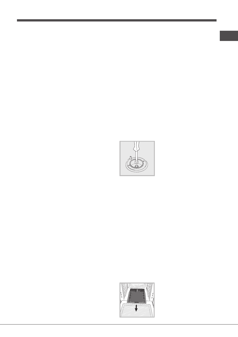
Replacing the nozzles for the hob
burners:
1. Remove the hob grids and slide
the burners off their seats.
2. Unscrew the nozzles using a 7
mm socket spanner (see figure), and
replace them with nozzles suited to
the new type of gas (see Burner and
nozzle specifications table).
3. Replace all the components by following the above
instructions in reverse.
Adjusting the hob burners’ minimum setting:
1. Turn the tap to the minimum position.
2. Remove the knob and adjust the regulatory screw, which
is positioned inside or next to the tap pin, until the flame is
small but steady.
! If the appliance is connected to natural gas, the adjustment
screw must be loosened in an anticlockwise direction.
3. While the burner is alight, quickly change the position of
the knob from minimum to maximum and vice versa several
times, checking that the flame is not extinguished.
! The hob burners do not require primary air adjustment.
Adapting the oven
Replacing the oven burner nozzle:
1. Open the oven door fully.
2. Remove the sliding oven base (see
figure).