Instruction and maintenance manual – Marwin Valve UT Series Pneumatic Actuators User Manual
Page 10
INSTRUCTION AND MAINTENANCE MANUAL
MARWIN UT DESIGN 2011 PNEUMATIC ACTUATORS
Page 10 of 10
3170 Wasson Road * Cincinnati, OH 45209 USA
Phone 513-533-5600 * Fax 513-871-0105
e-mail:
–ww
Bulletin IM-UT Dsgn2011_1114
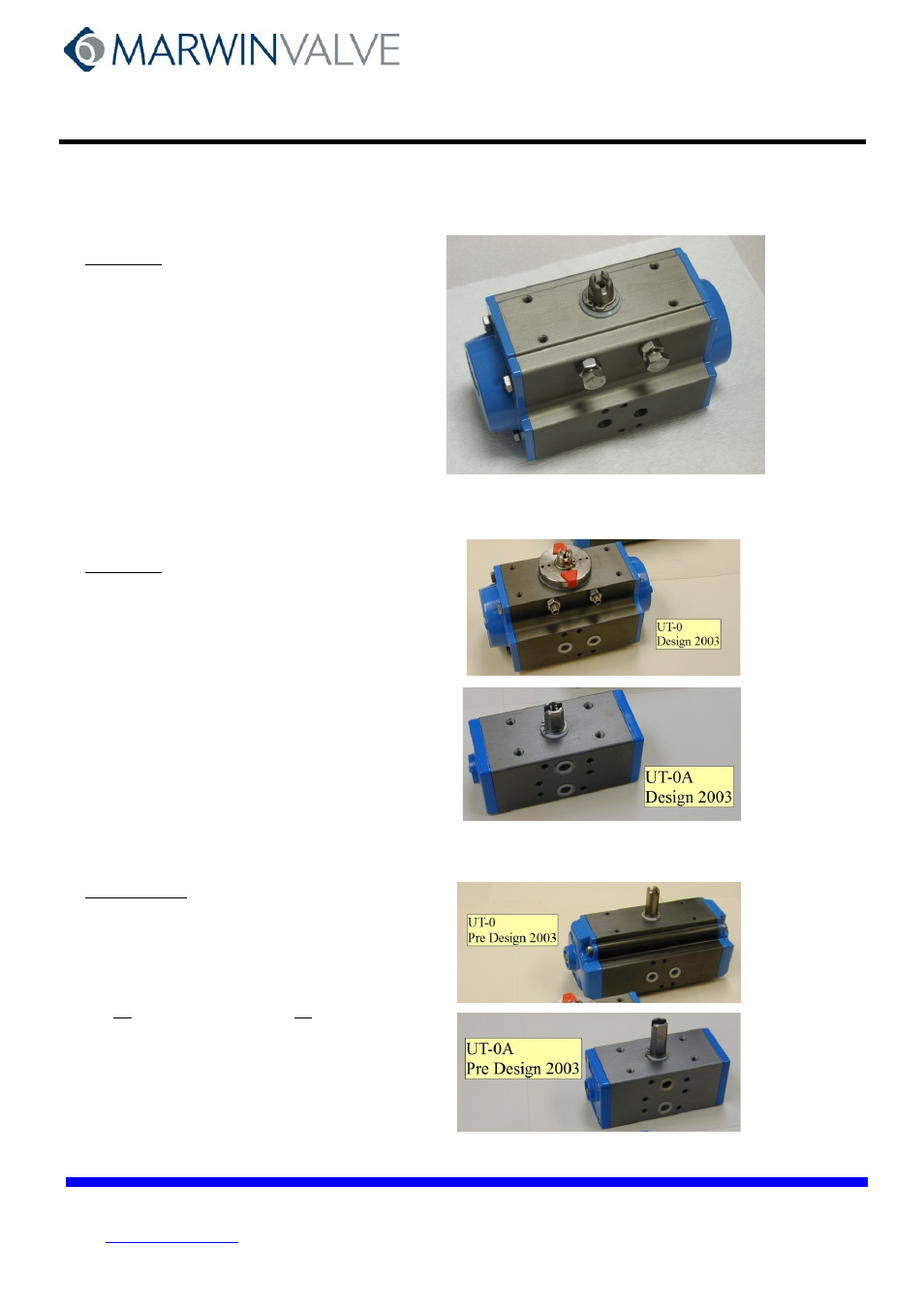
2011 Design (UT-1 Shown)
Representative of:
UT actuators 0A thru 7.5 after about 2011
Distinguishing features:
Adjusting screws on side, no hub on top,
“squared” ends
I&M
Bulletin IM-UT Dsgn2011_9999
2003 Design (UT-0 and UT-0A Shown)
Representative of:
UT actuators 0 thru 4 after about 2003
Distinguishing features (UT-0 thru UT-4.5):
Adjusting screws on side, hub on top,
“squared” ends
Distinguishing features (UT-0A)
Shorter shaft extension on top
I&M
Bulletin IM-UT(2003Design)-1211
Pre 2003 Design (UT-0 and UT-0A Shown)
Representative of:
All UT actuators 0A thru 7 prior to 2003
UT-0A, and UT-5 thru 7 only after 2003
Distinguishing features:
No adjusting screws on side, no hub on top,
Rounded ends with adjusting screws
I&M
Bulletin IM-UT(Pre2003Design)-1209