Instruction and maintenance manual – Marwin Valve UT Series Pneumatic Actuators User Manual
Page 6
INSTRUCTION AND MAINTENANCE MANUAL
MARWIN UT DESIGN 2011 PNEUMATIC ACTUATORS
Page 6 of 10
Bulletin IM-UT Dsgn2011_1114
3170 Wasson Road * Cincinnati, OH 45209 USA
Phone 513-533-5600 * Fax 513-871-0105
e-mail:
–ww
7.2
Disassembling
mod. UT-7 and UT-7.5
CAUTION: It is recommended to use suitable safety equipment during the handling for maintenance because of heavy and / or bulky parts.
1. Disconnect pneumatic and electric supplies from the actuator.
2. After having disconnected their power supply, remove carefully any accessory attached to the actuator, preventing any damage during the
handling.
3. Detach the actuator from the valve taking carefully note of all references that may be helpful for the attachment after maintenance.
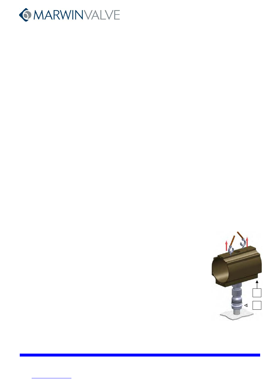
4. Place the actuator on a support with a square of the same size of the pinion (2) so as to easily execute the below listed operation (see Fig. 6).
5.
Before disassembling the actuator check from the label on the body whether it is a double acting (DA) or spring return (SR) type.
6. For DOUBLE ACTING ACTUATOR: Unscrew in crossed sequence the screws (14) for fastening the end caps (15) (see Fig. 7).
For SPRING RETURN ACTUATOR: Unscrew GRADUALLY in crossed sequence the screws (14) for fastening the end caps (15) (see Fig. 7).
NOTE: the screws are long enough to hold the pre-compressed springs (13) even if extended.
7. Loosen nuts (9) and unscrew completely screws (10) (see Fig. 8).
8. Rotate the cylinder (1) in clockwise direction (top view) holding the pinion (2) so as to release the rack of the pistons (12) from the pinion (2)
and to push the pistons towards the cylinder ends. Now both pistons (12) can be removed (see Fig. 9).
NOTE: Do not use compressed air to remove the pistons (12) from the cylinder (1)
9. Lay the actuator on one base of its cylinder (1) and unscrew the screws (11) in crossed sequence to remove the plate (7) (see Fig. 10).
10. Place the actuator on the support again.
11. Remove the snap ring (19) from the pinion (2), the washer (18), and the spacer (17) (see Fig. 11).
12. Gradually raise the cylinder (1), make sure that the pinion (2) gets extracted with special caution for all seatings (if necessary, use a rubber
hammer) (see Fig. 12).
14
15
15
2
9 10
Fig. 6
Fig. 7
Fig. 8
Fig. 9
----------------------------------------------------------------------------------------------------------------------------------------------------------------------------------------------------
19
12
18
17
2
1
2
12
1
7
11
Fig. 9
Fig. 10
Fig. 11
Fig. 12
1
2