Instruction and maintenance manual – Marwin Valve UT Series Pneumatic Actuators User Manual
Page 7
INSTRUCTION AND MAINTENANCE MANUAL
MARWIN UT DESIGN 2011 PNEUMATIC ACTUATORS
Page 7 of 10
3170 Wasson Road * Cincinnati, OH 45209 USA
Phone 513-533-5600 * Fax 513-871-0105
e-mail:
–ww
Bulletin IM-UT Dsgn2011_1114
8
Assembling
8.1
Assembling UT-0 thru UT-6.5
CAUTION: It is recommended to use suitable safety equipment during the handling for maintenance because of heavy and/or bulky parts.
1. Before assembling clean all components preferably with degreaser.
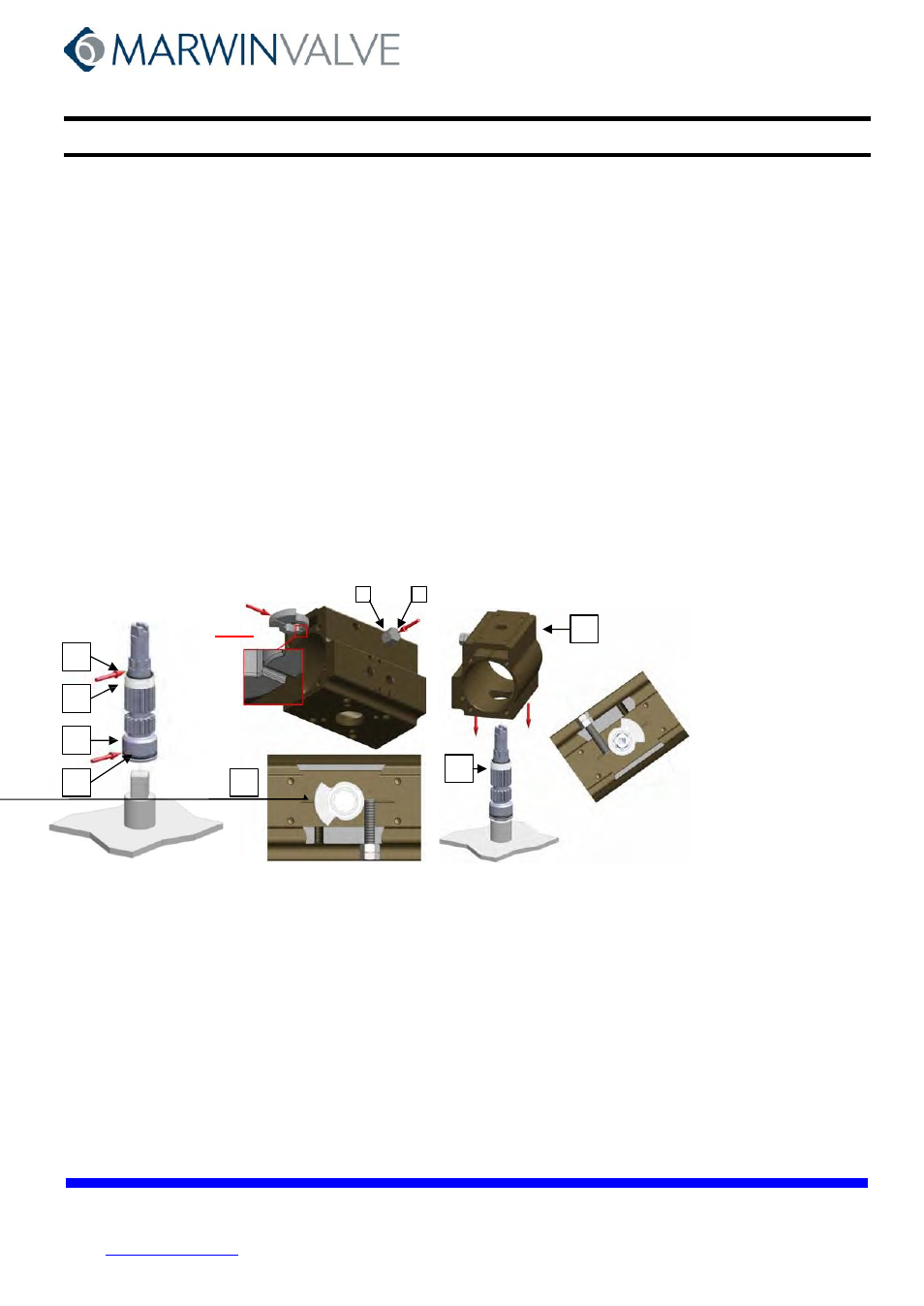
2. Place the pinion (2) on a support with a square of the same size of the female attachment. Make sure that the pinion is provided with
lower O-ring (3), spacer (4) and upper O-ring (5). Lubricate the O-rings (see arrows Fig. 13).
The recommended lubricating grease is “KLUBER” TRIBO STAR 1EP“
3. Screw down one adjustment screw (17) with nut (16) in the right adjustment hole of the cylinder (1) and let the cam (7) with ring (8) slide down on
the guiding rail on the cylinder (1) until it stops against the screw (see Fig.14 detail A) .
4. Lay the cylinder (1) down on the pinion (2) holding it with the NAMUR surface rotated by approximately 50° to the upper slot of the pinion,
(see Fig.15).
5. Fit on the pinion (2) the O-ring (6), the spacer (9), the washer (10), the snap ring (11) (see Fig. 16).
6. Grease the internal chamber of the cylinder (1) and both pistons (12) provided with O-ring (13) antifriction ring (14) and thrust block (15) - The
recommended lubricating grease is “KLUBER” TRIBO STAR 1EP“.
7. For the standard execution (clockwise pinion rotation looking at top when pistons travel toward each other) press the pistons (12) into the cylinder
(1) while turning the cylinder (1) in counterclockwise direction (top view) until the pistons come into contact (see Fig. 17).
8. Screw down the second adjustment screw (17) with nut (16) in the cylinder (1) and adjust the travel stop (see paragraph 9).
9. For DOUBLE ACTING ACTUATOR: Mount the end cap (21-22) with O-ring (24) and gasket (23) on the cylinder and screw down in crossed
sequence the screws (25) (see Fig. 18). Repeat the operation on the opposite side.
For SPRING RETURN ACTUATOR: Introduce the spring set (18-19-20) into the cylinder (1) and center them on the piston (12), then mount the
caps (21-22) with O-ring (24) and gaskets (23) centered on the springs (18-19-20). Note: the pistons
have to be in CLOSED (contracted) position. Tighten the screws (25) a little at a time in a crossed
sequence, compressing the springs uniformly, until the cap is completely closed (see Fig. 18). Repeat the
operation on the opposite side.
10. Execute some test cycles to check the correct functioning of the actuator before installing it.
DET. A
5
4
16
17
1
10
11
9
6
2
2
1
2
3
7
8
Fig. 13
Fig. 14
Fig. 15
Fig. 16
-------------------------------------------------------------------------------------------------------------------------------------------------------------------------------------------------
Fig.17
Fig.18
22
23
25
21
16
17
24
13
14
15
12
1
12