Instruction and maintenance manual, Ut-7 thru ut-7.5, Marwin ut design 2011 pneumatic actuators – Marwin Valve UT Series Pneumatic Actuators User Manual
Page 4
INSTRUCTION AND MAINTENANCE MANUAL
MARWIN UT DESIGN 2011 PNEUMATIC ACTUATORS
Page 4 of 10
Bulletin IM-UT Dsgn2011_1112
3170 Wasson Road * Cincinnati, OH 45209 USA
Phone 513-533-5600 * Fax 513-871-0105
e-mail:
–ww
6.2
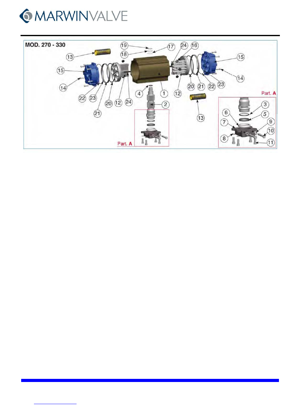
Exploded view mod. UT-7 and UT-7.5
Pos.
Description
Material
Treatment
Quan.
DA
Quan.
SR
1 Body
Extruded aluminum
Hard anodized
1
1
2 Pinion, anti-blowout
Steel
Nickel plated
1
1
*
3
O-ring, pinion, lower
NBR
1
1
*
4
O-ring, pinion, upper
NBR
1
1
*
5
Antifriction ring, pinion
PTFE 15% graphite
1
1
*
6
Antifriction ring, pinion
PTFE
1
1
7 Housing, stop assembly
GGG40
Painted
1
1
8 Washer
Stainless steel
4
8
9 Nut, stop bolt retaining
Stainless steel
2
2
10 Bolt, stop
Steel
Zinc plated
2
2
11 Bolt, housing, stop assembly
Stainless steel
4 [8]
4 [8]
12 Piston
Die cast aluminum
2
2
13 Spring, pre-compressed
Steel
Painted
See Spring Set
14 Bolt, end cap
Stainless steel
12 [16]
12 [16]
15 End cap
Die cast aluminum
Painted
2
2
*
16 Thrust block
POM
6 [8]
6 [8]
*
17 Spacer ring
POM
1
1
18 Washer, pinion
Stainless steel
1
1
19 Snap ring
Steel
Nickel plated
1
1
*
20 O-ring, pinion
NBR
2
2
*
21 Antifriction ring
PTFE 15% graphite
2
2
22 O-ring, end cap
NBR
2
2
23 O-ring
NBR
4 [2]
4 [2]
24 Anti-blowout key
POM
2
2
[x] UT-7 only
* Part subject to wear
UT-7 THRU 7.5
SPRING SETS
SPR. NO.
NO. SPR. EA. SIDE
01
2 / 3
02
3 / 3
03
3 / 4
04
4 / 4
05
4 / 5
06
5 / 5
06
5 / 6
07
6 / 6
UT-7 THRU UT-7.5