High flow – Precision Medical HeliO2 Blenders User Manual
Page 22
Heliox / Oxygen Blender Service Manual
Page 20
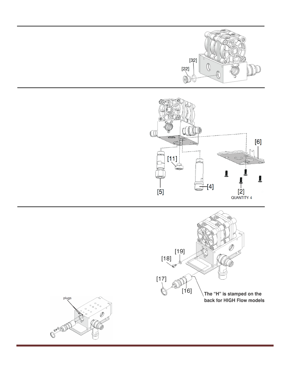
HIGH FLOW
Figure J
10. Replace O-ring [32] on plug [22]. Install plug and tighten.
Figure K
11. Start threads of new alarm assembly [11] by
hand, tighten with Retaining Ring Pliers, ensure
not to bend reed.
12. Attach bottom cover [6] using four flat head
screws [2].
13. Install new Heliox inlet assembly [4], torque to
10 ft-lbs (13.6 Nm).
14. Install new Oxygen inlet assembly [5] torque to
10 ft-lbs (13.6 Nm). Oxygen inlet assembly has
left handed threads.
15.
Install new Heliox inlet assembly [4], torque to
10 ft-lbs (13.6 Nm).
Figure L
16. Lubricate proportioning valve bore with Krytox
GPL 106.
17. Align the (3) holes on the proportioning valve
assembly [16] equal distance between the (2)
plugs and push in. *Reference drawing below.
18. Replace washer [19] and phillips head screw [18].
19. Place new resistance ring [17] in its place on the
proportioning valve assembly.
*Proportional valve assembly inserted, with the
“H” stamped on back for High Flow Model.