Retrotec FanTestic Integrity (ISO) User Manual
Page 36
rev-2014-10-27
Page 36 of 50
©Retrotec Inc. 2012
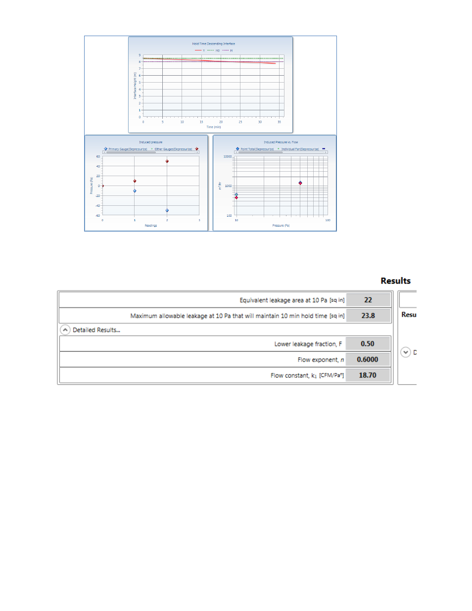
3.8 Total Enclosure Leakage and Lower leaks test results
“Flow constant” , k
1
and “Flow exponent”, n
A Building Leakage Curve is created after at least two “Test Fan” data points have been
entered, which is used to estimate the leakage rate of the building at any pressure. The
Building Leakage Curve is defined by the following equation:
Q = k
1
x P
n
where:
Q is the air “Flow” rate through the fan (CFM or m
3
/h)
k
1
is the “Flow constant, (CFM/Pa
n
or (m
3
/h)/Pa
n
)
P is the pressure difference between the inside and outside of the enclosure (Pa)
n is the “Leakage exponent”
Example: calculate the airflow needed to create a 5 Pa pressure if:
k
1
= 110.2 n = 0.702
Q, the airflow (at 5 Pa) = 110.2 x 5
0.702
= 341 CFM.