Riello UPS Sentinel Dual (High Power) (3.3 - 10 kVA) User Manual
Page 53
53
U
SE
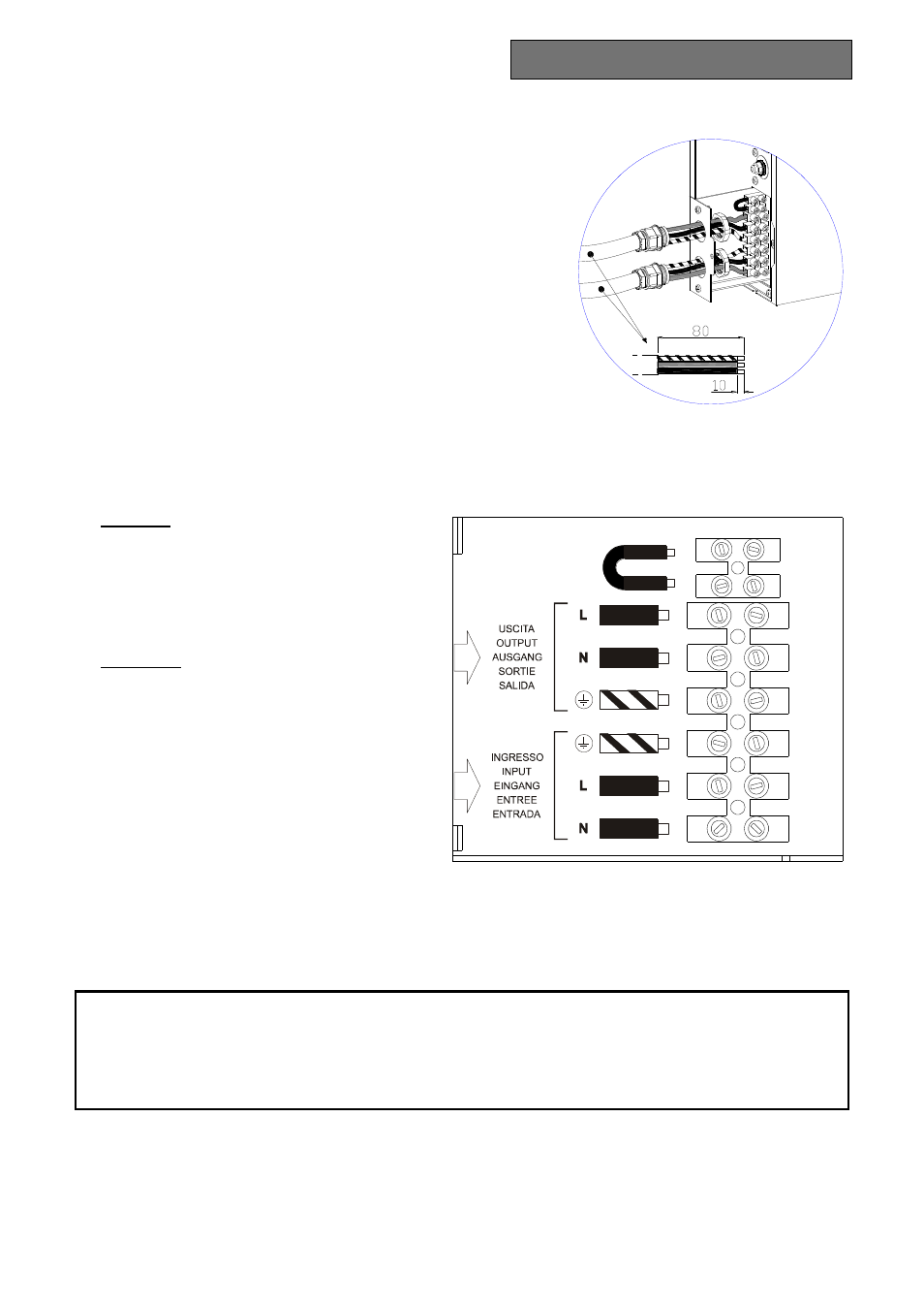
4. Use 3-pole cables with 4 mm
2
section. With reference to the
figure shown at the side:
- Insert the cable from the 32A magneto-thermal switch into
cable guide P1 (input line).
- Insert the cable from the load into cable guide P2 (output
line).
- Strip the cables observing the measurements provided.
- Insert the stripped end in the terminals provided.
5. Connect the wires to the relative terminals strictly following the instructions set out below:
Input line
a - Ensure that the magneto-thermal switch
upstream is open.
b - Connect the earth wire to terminal 3.
c - Connect the neutral wire to terminal 1.
d - Connect the phase wire to terminal 2.
Output line
a - Connect the earth wire to terminal 4.
b - Connect the neutral wire to terminal 5.
c - Connect the phase wire to terminal 6.
6. Ensure that a jumper is connected at
terminals 7 and 8; this is needed for the
correct operation of the UPS.
7. Secure the cable guides to the flange, close the drawer and secure it with the screw removed previously.
A WARNING LABEL MUST BE AFFIXED TO ALL MAINS POWER ISOLATING SWITCHES INSTALLED FAR FROM THE
UPS AREA, IN ORDER TO REMIND SUPPORT SERVICE PERSONNEL THAT THE CIRCUIT IS CONNECTED TO A UPS. THE
LABEL MUST CARRY THE FOLLOWING MESSAGE:
ISOLATE THE UNINTERRUPTIBLE POWER SYSTEM (UPS)
BEFORE WORKING ON THIS CIRCUIT
P1
P2
B y - P a s s
M a n u t e n z i o n e R em oto
Remote Maintenance
By-Pass
1
2
3
4
5
6
7
8