Rear connectors, J1 main interface connector input – Rosen Aviation 0604 Series : Rosenview VX User Manual
Page 8
Rosen Aviation
RosenView VX Technical Manual
Document Number: 100640
Revision: G
Date: 9/19/12
Template: 4.4.1.6FM1; Revision A; 31 May, 2012
Page 8 of 23
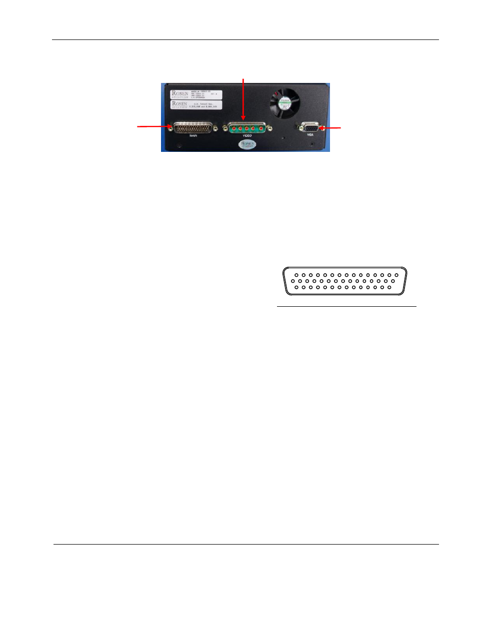
3.2. Rear Connectors
Figure 4 RosenView VX rear panel view
3.2.1. J1 Main Interface Connector Input
Note: The following connector inputs are for reference only. For the latest pinout
information, see the Outline and Installation drawing.
Connector Type: DB44-HD Male
Rosen Connector Kit: 0300-038 (included)
Pin #
Signal
1
28V return
2
ARINC-429 in 1B
3
ARINC-429 in GND
4
ARINC-429 in 2B
5
RS-232 RX1 (Control panel)
6
RS-232 RX2 (GPS)
7
RS-232 2 (GND)
8
Discrete Input 2 (future development)
9
Volume Up Discrete Output
†
10
Aux1 Audio L Low In
11
Aux1 Audio R Low In
12
Aux2 Audio L Low In
13
Aux2 Audio R Low In
14
DVD Audio L Out
15
DVD Audio R Out
16
28V In
17
NC
18
ARINC-429 In A1
19
ARINC-429 2 GND
20
ARINC-429 In A2
21
RS-232 TX1 (Control panel)
22
RS-232 1 GND
23
GND
1
15
30
44
Power and
data input
Video output
Monitor
RGB
16
24
Rear view of RosenView VX Main Connector