Notice – Thermo Pride Heat Pump Coil LX-13 User Manual
Page 5
5
SECTION IV: COIL INSTALLATION
FURNACE ASSEMBLY - MC & FC
These coils are factory shipped for installation in either upflow or down-
flow applications with a minor conversion.
For Upflow Application:
1.
Position the coil casing over or under the furnace opening as
shown in Figure 5 after configuring coil flanges as required see
“Coil Flange” section below and refer to Figure 7.
2.
Slide up the sides and back flange and tight the 6 screws that hold
them. Refer to Figure 6.
3.
Unscrew the front flange and move it to the top to align it to the
rest of the flanges allowing to screw it back to the brace using the
2 holes in the bottom of the front flange. Refer to Figure 6.
4.
Place the ductwork over the coil casing flange and secure.See
sections on "Refrigerant L ine Connections" and "Condensate
Drain Connections". One mounting plate is provided with the coils.
For Downflow Application:
1.
Position the coil casing over or under the furnace opening as
shown in Figure 5 after configuring coil flanges as required see
“Coil Flange” section below and refer to Figure 7.
2.
Remove all 8 screws from flangs and position them at the bottom
of the casing for the alternate position. Refer to Figure 7.
3.
Place the ductwork over the coil casing flange and secure.See
sections on "Refrigerant Line Connections" and "Condensate
Drain Connections". One mounting plate is provided with the coils
COIL FLANGE - FOR DOWNFLOW AND HORIZONTAL
LEFT KIT INSTALLATION
The coils include removable flanges to allow proper fit up with furnaces
or two-piece air handlers having various inlet and outlet flange configu-
rations. The two flanges are attached to the top of the coil in the factory
during production. If the installation requires the flanges to be moved to
the bottom of the coil, remove the screws attaching the flanges to the
top of the coil casing. Next, install the flanges to the bottom of the coil
casing using the same screws. Refer to Figure 7.
The additional holes in the upper area of the flanges may be used to
attach the coil to the furnace or two-piece air handler. This is done by
installing field-supplied screws through the flanges into the inside of the
furnace or two-piece air handler casing.
The front flange is also designed so that it can be rotated 180 degrees
and re-installed. In this mounting configuration the front flange will
extend further to the front of the coil casing to accommodate furnaces
or two-piece air handlers that have a greater front-to-back dimension
than the coils.
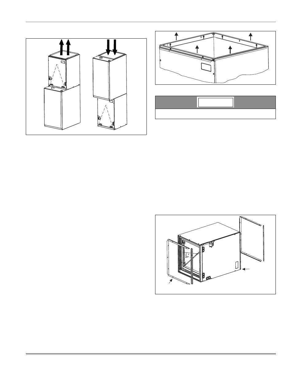
FIGURE 5: Vertical Applications
UPFLOW
DOWNFLOW
Furnace
Furnace
FIGURE 6: Coil Flange Placement
When installing this coil with an oil furnace, a minimum of six inches
clearance should be maintained from the top of the heat exchanger.
FIGURE 7: Coil Flange
NOTICE
Alternate
Flange Location
Factory
Flange
Location