Notice – Thermo Pride Heat Pump Coil LX-13 User Manual
Page 6
6
FURNACE ASSEMBLY - (MC ONLY)
MC coils are supplied ready to be installed in a horizontal position. A
horizontal pan is factory installed. MC coils should be installed in all hor-
izontal applications with the horizontal drain pan side down.
For horizontal left hand applications no conversion is required to an MC
coil when used with a downflow/horizontal furnace. A mounting plate,
supplied with every coil should always be installed on the side desig-
nated as top side. See Figure 8 & 9.
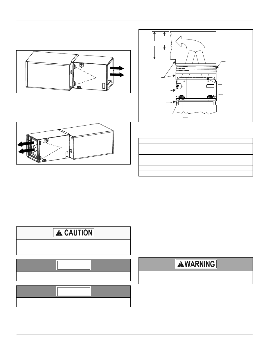
FURNACE ASSEMBLY - PC
These upflow coils are designed for installation on top of upflow fur-
naces only.
If the coil is used with a furnace of a different size, use a 45° transition
to allow proper air distribution through the coil.
1.
Position the coil casing over the furnace opening as shown in Fig-
ure 10.
2.
Place the ductwork over the coil casing flange and secure.
3.
Check for air leakage between the furnace and coil casing and
seal appropriately.
Dimension “C” should be at least 2/3 of dimension “D”. See Figure 12.
CRITICAL COIL PROJECTION
The coil assembly must be located in the duct such that a minimum dis-
tance is maintained between the top of the coil and the top of the duct.
Refer to Table 6.
SECTION V: DUCT CONNECTIONS
Air supply and return may be handled in one of several ways best
suited to the installation. Upflow, horizontal or downflow applications
may be used.
The vast majority of problems encountered with combination heating
and cooling systems can be linked to improperly designed or installed
duct systems. It is therefore highly important to the success of an instal-
lation that the duct system be properly designed and installed.
Use flexible duct collars to minimize the transmission of vibration/noise
into the conditioned space.
FIGURE 8: Horizontal Right Application
FIGURE 9: Horizontal Left Application
Do not drill any holes or drive any screws into the front duct
flange on the coil in order to prevent damaging coil tubing (see
Figure 12).
When installing this coil with an oil furnace, a minimum of six inches
clearance should be maintained from the top of the heat exchanger.
Refer to the heat pump add-on control instruction before installing
an add-on heat pump coil.
Furnace
Furnace
NOTICE
NOTICE
FIGURE 10: Upflow Coil Installation
TABLE 5: Coil Projection Dimensions - PC Coils
COIL SIZE
DIMENSION “C” INCH
PC18
3-1/2
PC24
4-1/2
PC30, PC32, PC35
4-1/2
PC42, PC43, PC36, PC37
5-1/2
PC48
6-1/2
PC60
9
Use 1/2" screws to connect ductwork to unit. If pilot holes are
drilled, drill only through field duct and unit flange.
Flexible Duct
Collar
DO NOT Drill or
Screw this Flange
Field
Fabricated
Ductwork
Upflow Coil
Upflow Furnace
Secondary Drain
Primary Drain
D
C
(Min.)
Alternate
Drain Location