Thermo Pride Spirit Gas TG8S Single Stage PSC 80% User Manual
Page 16
998491-UIM-B-1013
16
Johnson Controls Unitary Products
Single-Wire Twinning Operation
Heating - On a call for heat (W signal) from the wall thermostat, both
furnaces will start the ignition sequence and the burners on both fur-
naces will light. About thirty seconds after the burners light, the blowers
on both furnaces will come on in heating speed. When the thermostat is
satisfied, the burners will all shut off and, after the selected blower off
delay time, both blowers will shut off at the same time. The twinning
control ensures that both blowers come on and shut off at the same
time.
Cooling - On a call for cooling (Y signal) from the wall thermostat, both
furnace blowers will come on at the same time in cooling speed. When
the thermostat is satisfied, both blowers will stay on for 60 seconds,
then will shut off at the same time.
Continuous Fan - On a thermostat call for continuous fan (G signal),
both furnace blowers will come on at the same time in cooling speed
and will stay on until the G signal is removed.
STAGING
This control can also be used along with a two-stage wall thermostat to
stage two twinned furnaces, making them operate like a single two-
stage furnace. This allows only one furnace to supply heat during times
when the heat output from one furnace is sufficient to satisfy the
demand. When one duct system is used for two furnaces, it is neces-
sary that the two blowers operate in unison. The twinning function of
this board ensures that both blowers turn on and off simultaneously,
and operate on the same blower speed. Even when only one furnace is
supplying heat, both furnace blowers must run.
Single-Wire Staging
The single-wire twinning feature of this board can also be used for stag-
ing of two furnaces. With this feature, a single wire is connected
between the TWIN terminal on one furnace board to the TWIN terminal
on the second furnace board. The board then communicates the blower
status from one furnace to the other along this wire. This communica-
tion makes the second furnace blower come on at the same time, and
on the same speed, as the first furnace blower. To ensure stable com-
munication, the common terminal of each control must be connected.
Single-Wire Staging Instructions
Connect the control wiring as shown in Figure 22.
1. Connect the low voltage wiring from the wall thermostat to the termi-
nal strip on the control board of Furnace #1. For staging applica-
tions, the wire from thermostat W1 is connected to the W connection
on the board on Furnace #1. The wire from thermostat W2 is con-
nected to Furnace #2 through a separate relay, as described below.
2. Connect a wire from the TWIN terminal of Furnace #1 to the TWIN
terminal of Furnace #2.
3. Install a separate 24V relay as shown in the diagram below. Use of
this relay is required, as it ensures that the transformers of the two
furnaces are isolated, thus preventing the possibility of any safety
devices being bypassed.
4. Connect the common between furnace #1 and furnace #2.
Single-Wire Staging Operation
Heating - On a call for first-stage heat (W1 signal) from the wall thermo-
stat, Furnace #1 will start the ignition sequence and the burners will
light. About thirty seconds after the burners light, the blowers on both
furnaces will come on in heating speed. When the thermostat is satis-
fied, the burners will shut off and, after the selected blower off delay
time, both blowers will shut off at the same time. On a call for second
stage of heat, the burners of Furnace #2 will also light and both blowers
will run. The twinning control ensures that both blowers come on and
shut off at the same time.
Cooling - On a call for cooling (Y signal) from the wall thermostat, both
furnace blowers will come on at the same time. When the thermostat is
satisfied, both blowers will stay on for 60 seconds, then will shut off at
the same time.
Continuous Fan - On a thermostat call for continuous fan (G signal),
both furnace blowers will come on at the same time in cooling speed
and will stay on until the G signal is removed.
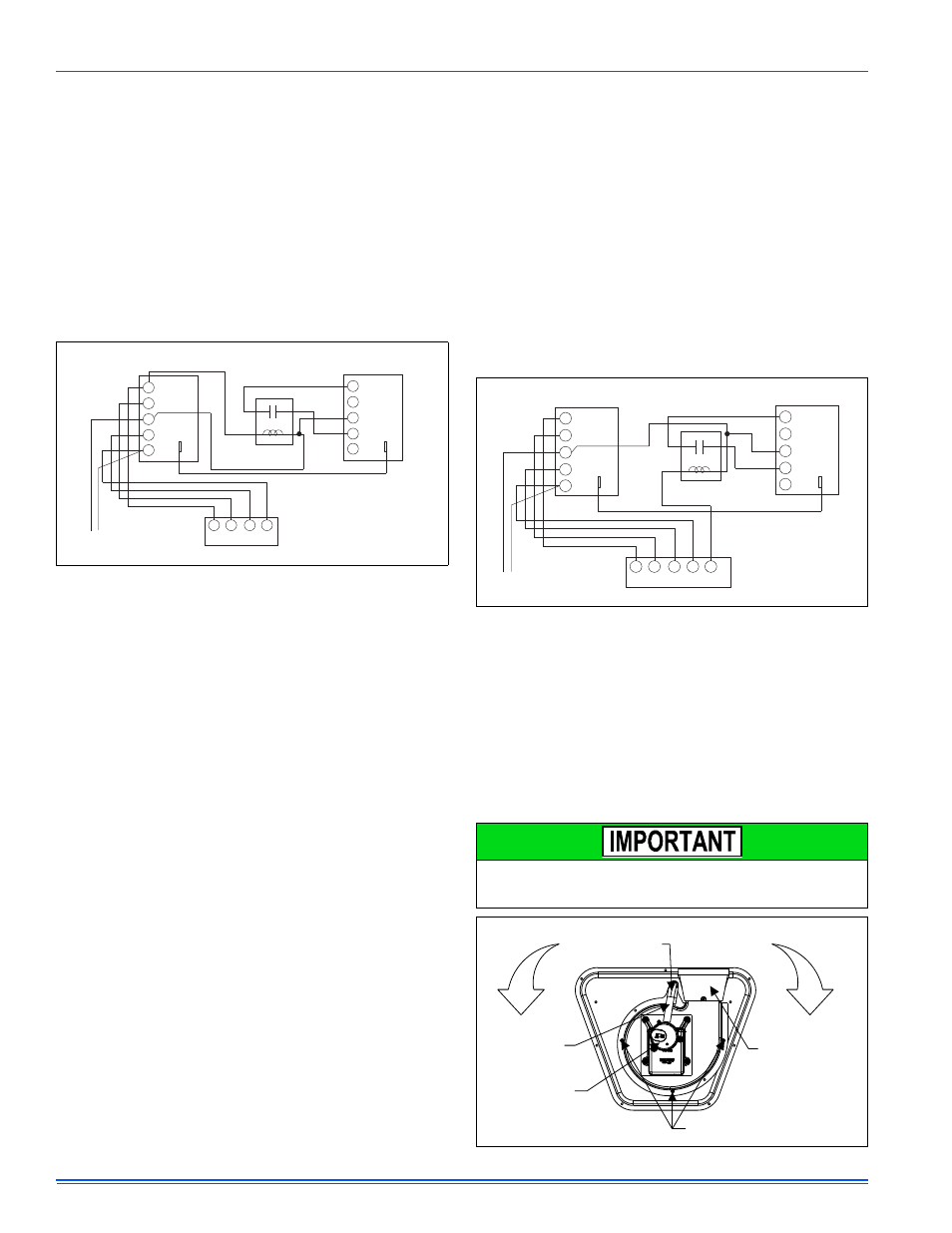
SECTION VII: VENT SYSTEM
VENT CONNECTIONS
All models are provided with a flue transition that is sized for 4” diame-
ter vent connections. If a larger size vent connector is required, that
connection must be installed external to the furnace. Figure 22 shows
the furnace as it is shipped from the factory. To convert to a horizontal
or downflow position, remove the four screws that secure the inducer
assembly and rotate 90° being careful not to damage the gasket. Rein-
stall screws. Remove cap from appropriate vent outlet location on the
cabinet, cut insulation in cabinet to same size as the hole provided and
reinstall cap in the hole in the top panel.
FIGURE 20: Single Wire Twinning Wiring Diagram
W
G
C
R
Y
TWIN
TO A/C
WALL THERMOSTAT
W
G
R
Y
ISOLATION
RELAY
FURNACE 2
CONTROL BOARD
W
G
C
R
Y
TWIN
FURNACE 1
CONTROL BOARD
FIGURE 21: Single Wire Staging Wiring Diagram
In downflow applications, do not block the combustion air inlet. The
furnace must be installed on a coil cabinet or subbase to allow com-
bustion air to enter the burner compartment.
FIGURE 22: Combustion Air Inducer
W
G
C
R
Y
TWIN
TO A/C
WALL THERMOSTAT
W1 G
R
Y
ISOLATION
RELAY
FURNACE 2
CONTROL BOARD
W
G
C
R
Y
TWIN
FURNACE 1
CONTROL BOARD
W2
COMBUSTION AIR INDUCER
90°
90°
Mounting Screw
(Remove)
Flue Transition
(Do Not Remove)
Mounting Screw
(Remove)
Pressure
Switch
Pressure Switch
Tube Routing