Installation instructions, Brake adjustment instructions – SAF-HOLLAND XL-AS11011OM CBX40/CB-4000 Slider Suspension Systems User Manual
Page 16
Advertising
XL-AS11011OM-en-US Rev F · 2014-06-13 · Amendments and Errors Reserved · © SAF-HOLLAND, Inc., SAF-HOLLAND, HOLLAND, SAF,
and logos are trademarks of SAF-HOLLAND S.A., SAF-HOLLAND GmbH, and SAF-HOLLAND, Inc.
Installation Instructions
16
NOTE: Alignment plates are NOT welded to the frame
bracket, but are free to rotate.
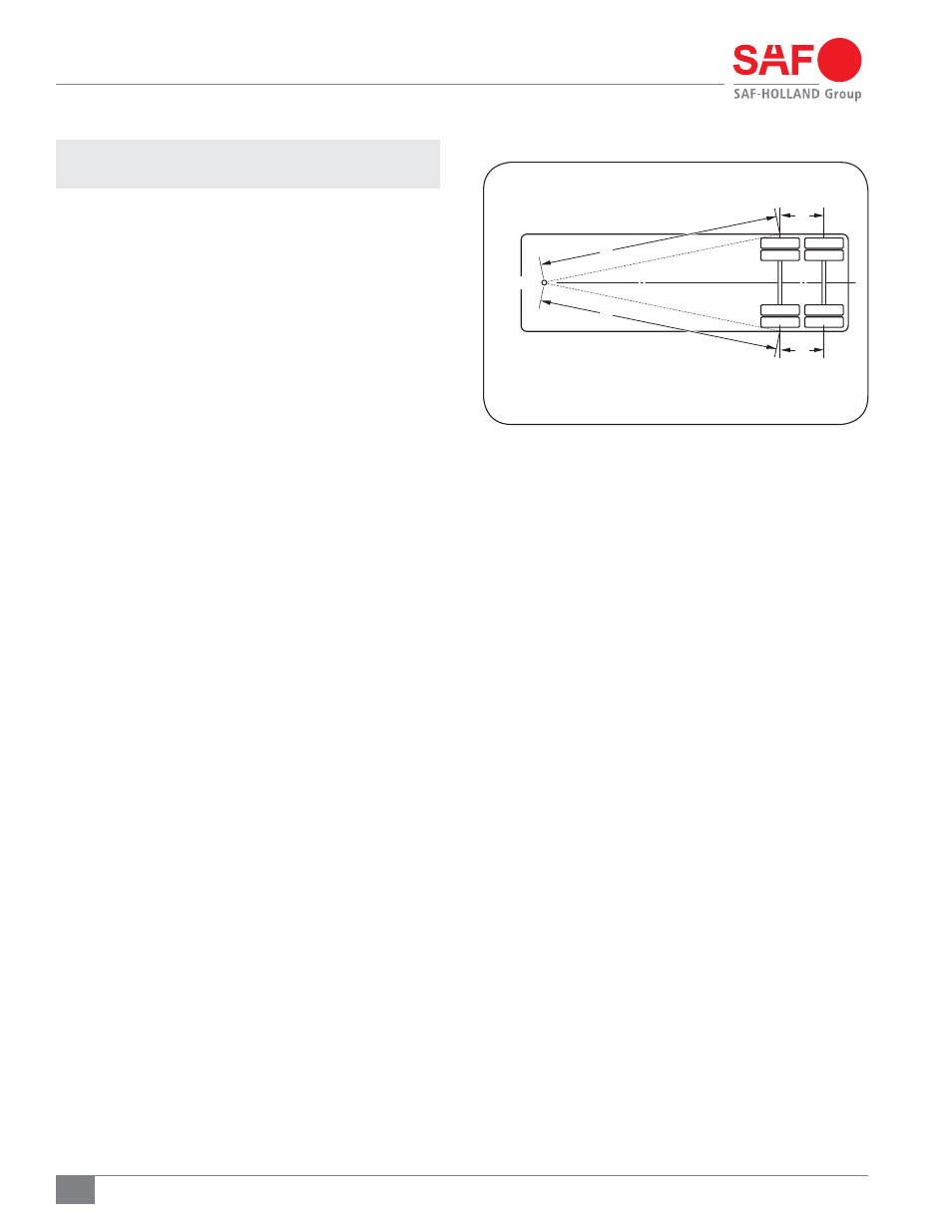
2. Relocate the slider to the forward position and recheck the
king pin alignment. Variance in dimensions “A” and “B”
(Figure 22) indicates there are discrepancies in lock pin
hole location.
14. Brake Adjustment Instructions
Brakes should be adjusted per axle and brake manufacturer’s
specifications.
Figure 22
A
KINGPIN
B
D
C
A = B ± 1/8" (3 MM)
C = D ± 1/16" (1.6 MM)
Advertising