Operation instructions – SAF-HOLLAND XL-AS11011OM CBX40/CB-4000 Slider Suspension Systems User Manual
Page 19
XL-AS11011OM-en-US Rev F · 2014-06-13 · Amendments and Errors Reserved · © SAF-HOLLAND, Inc., SAF-HOLLAND, HOLLAND, SAF,
and logos are trademarks of SAF-HOLLAND S.A., SAF-HOLLAND GmbH, and SAF-HOLLAND, Inc.
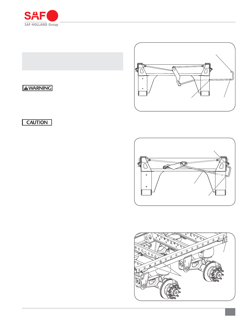
b. Lift and push the pull arm handle from the disengaged
position (Notch 2 - Figure 27) to the engaged
position (Notch 1 - Figure 28).
NOTE: If your slider is equipped with an air release pin
mechanism, push the air release control valve
knob to engage the lock pins.
8. Visually check that the lock pins are fully engaged and
extend through the holes in the upper rail (Figure 29).
An unsecured slider box can cause loss
of vehicle control which, if not avoided,
could result in death, serious injury or
property damage.
9. Visually check that the manual stop bar is properly installed
directly behind slide box (Figure 29).
Failure to properly install or position the
manual stop bar could result in improper
trailer load distribution which, if not
avoided, could result in damage to the
suspension or trailer parts.
Operation Instructions
19
PULL ARM
HANDLE
DISENGAGED POSITION
NOTCH 1
NOTCH 2
ENGAGED POSITION
NOTCH 1
NOTCH 2
MANUAL
STOP BAR
LOCK PINS
ENGAGED
IN SLIDER RAIL
Figure 28
Figure 29
Figure 27
PULL ARM
HANDLE