Operation instructions, Slider repositioning instructions – SAF-HOLLAND XL-AS11011OM CBX40/CB-4000 Slider Suspension Systems User Manual
Page 18
XL-AS11011OM-en-US Rev F · 2014-06-13 · Amendments and Errors Reserved · © SAF-HOLLAND, Inc., SAF-HOLLAND, HOLLAND, SAF,
and logos are trademarks of SAF-HOLLAND S.A., SAF-HOLLAND GmbH, and SAF-HOLLAND, Inc.
PULL ARM
HANDLE
LOCK PINS
ENGAGED
ENGAGED POSITION
NOTCH 1
NOTCH 2
Operation Instructions
18
Figure 25
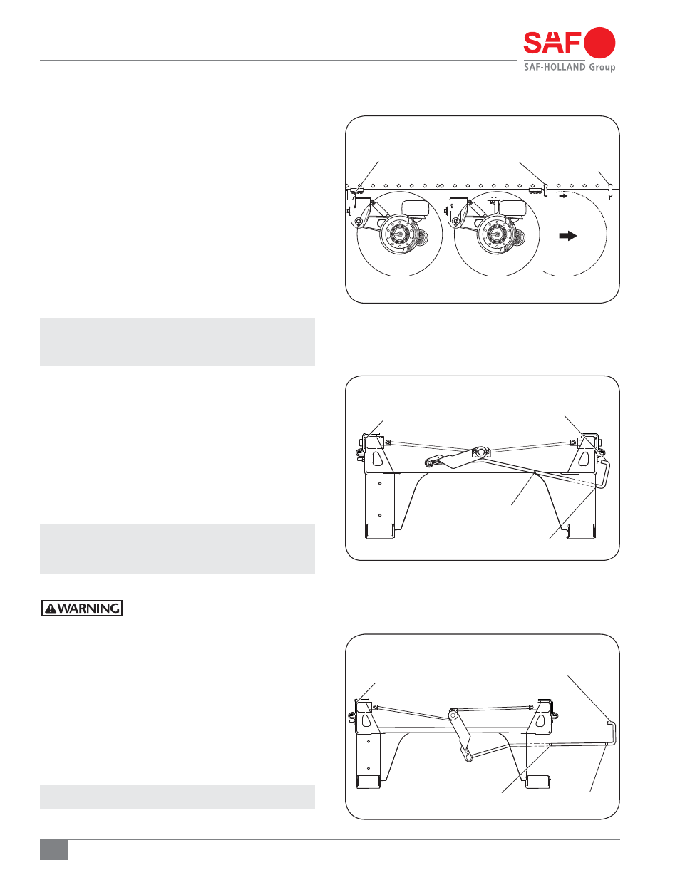
Figure 26
Figure 24
16. Slider Repositioning Instructions
1. With the vehicle on a level surface, set the tractor and
trailer brakes and locate the slider QWIK RELEASE
®
pull
arm handle (Figure 24), or air release control valve.
2. To reposition the slider, remove the manual stop bar
and relocate to desired location – rearward of slide box
if moving rearward, or forward of slide box if moving
forward (Figure 24).
If repositioning the slider forward, remove the manual
stop bar and relocate directly behind slide box after the
slider is moved to final position.
3. Lift and pull the QWIK RELEASE
®
pull arm handle from
the engaged position (Notch 1 - Figure 25) to the
disengaged position (Notch 2 - Figure 26).
NOTE: If your slider is equipped with an air release pin
mechanism, pull the air release control valve knob
to disengage the lock pins.
4. Visually check to ensure the lock pins are in the disengaged
position, and that the QWIK RELEASE
®
pull arm handle is
locked (Notch 2 - Figure 26).
When lock pins have properly disengaged, proceed to
Step 6.
If lock pins fail to disengage, proceed to Step 5.
5. If the QWIK RELEASE
®
pull handle is in the notch 2
position but the lock pins fail to retract and are still
in the engaged position, the QWIK RELEASE
®
pull
arm is in an armed, ready to unlock position.
NOTE: The QWIK RELEASE
®
torsion spring will
automatically retract the lock pins when
the pressure on the lock pins is released.
a. Release the tractor brakes.
Failure to verify the area is clear of
others before moving the vehicle could
result in death or serious injury.
b. Gently rock the tractor and trailer fore and aft while
listening for the lock pins to disengage.
c. After the “metallic clang” of the lock pins disengaging
is heard, reset the tractor brakes, and visually verify
that the lock pins have been properly disengaged.
6. When the lock pins have disengaged – slowly reposition
the tractor until the slide box contacts the manual stop
bar (Figure 24).
7. a. Set the tractor brakes.
NOTE: Trailer parking brakes should still be engaged.
RELOCATED
MANUAL
STOP BAR
MANUAL
STOP BAR
PULL ARM
HANDLE
PULL ARM
HANDLE
DISENGAGED POSITION
NOTCH 1
NOTCH 2
LOCK PINS
DIS-ENGAGED