Network cabling and configuration – ProSoft Technology WRC-CANX User Manual
Page 14
Western Reserve Controls
WRC-CANX-xx Series 4
PUB 14.1
User’s Manual
10
4.5. Network Cabling and Configuration
This section provides general guidelines for connecting DeviceNet and SDS systems. You can
find detailed specifications in the appropriate ODVA DeviceNet and Honeywell SDS specifications.
4.5.1. Cable Lengths
The following provide cable length limits for DeviceNet and SDS systems.
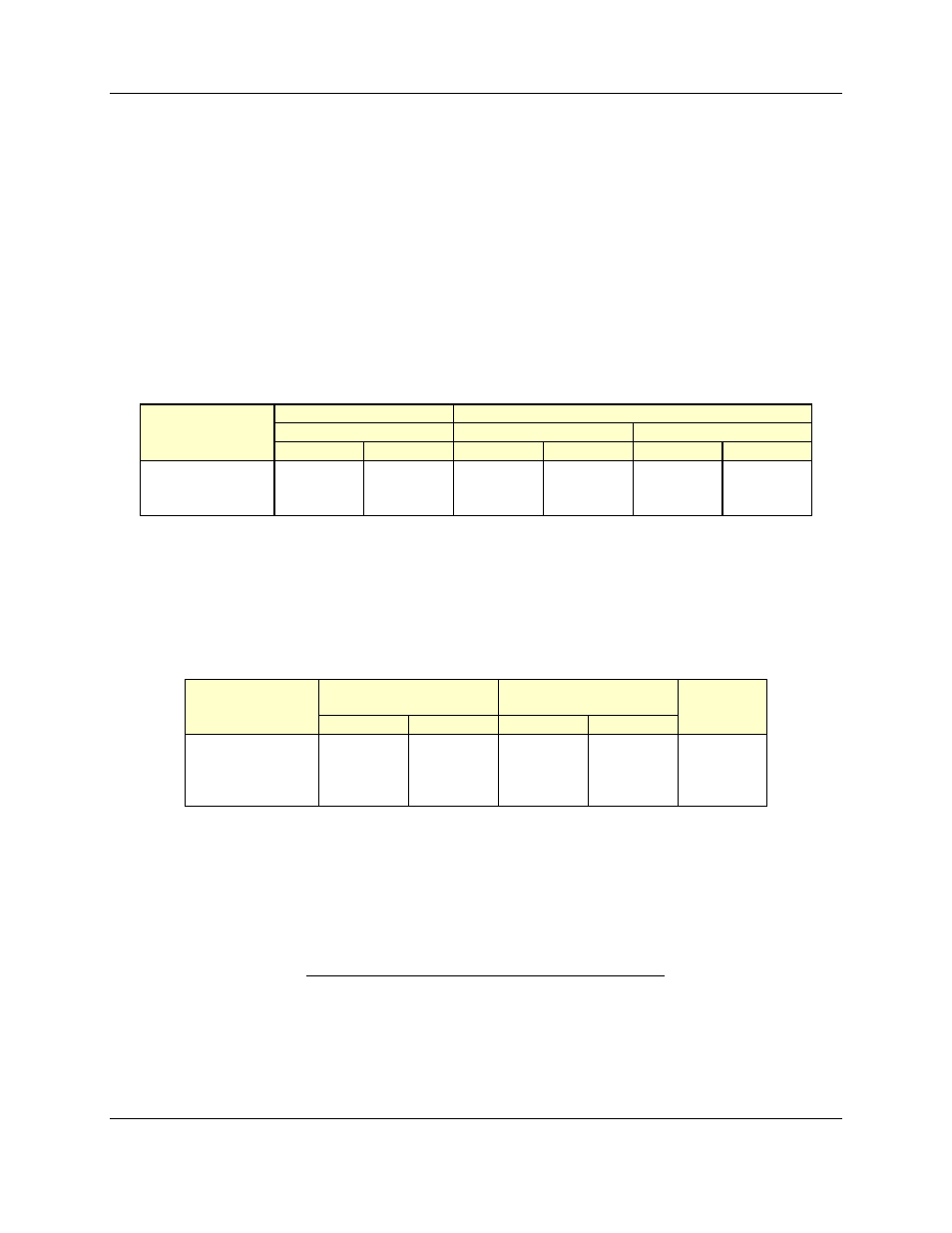
Table 4-5 Network Maximum Lengths - DeviceNet
Baud Rate
Trunk Line Length
Drop Length
Maximum Distance
Maximum
Cumulative
Meters
Feet
Meters
Feet
Meters
Feet
125 Kbits/s
500 m
1640 ft
6 m
20 ft
156 m
512 ft.
250 Kbits/s
250 m
820 ft
6 m
20 ft
78 m
256 ft.
500 Kbits/s
100 m
328 ft
6 m
20 ft
39 m
128 ft.
DeviceNet has a limit of 64 nodes per network for any baud rate. The CANX does not count as an
addressed device.
Table 4-6 Network Maximum Lengths - SDS
Baud Rate
Trunk Line Length
(maximum)
Drop Length
(maximum)
No.
Nodes
Meters
Feet
Meters
Feet
125 Kbits/s
457.2
1500
3.6
12
64
250 Kbits/s
182.8
600
1.8
6
64
500 Kbits/s
91.4
300
0.9
3
64
1 Mbits/s
22.8
75
0.3
1
32
SDS has a limit of 32 nodes per network for any baud rate. The CANX does not count as an
addressed device.
4.5.2. Network Termination
A CAN-Bus system must be terminated at each end of the trunk line. The host controller and
the last device (CAN-Bus Extender or other DeviceNet node) on the network section must always be
terminated to eliminate reflections, even if only two nodes are present. Follow the information below when
using a CANX.
The CANX Series 4 has built-in terminators, which can selectively included or omitted from the
network. To include the on-board terminator on side A, install jumper W1; or remove the W1 jumper if the