ProSoft Technology WRC-CANX User Manual
Page 31
Western Reserve Controls
WRC-CANX-xx Series 4
PUB 14.1
User’s Manual
27
•
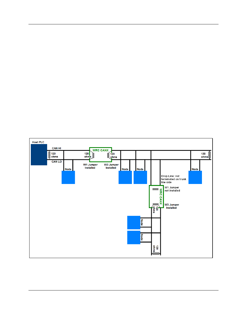
The WRC CANX has two user-selectable 121-ohm resistors on board. Keeping the plastic
jumpers, which are installed on all units at the factory, on W1 and W3 will keep these resistors
in the circuit, across the CAN data lines. In this case, the user needs only to terminate the other
end of each side of the bus with a 120 ohm resistor to insure correct termination on Network
side A (on one side of the CANX) and Network side B (on the other side of the CANX). If your
network is already terminated at the beginning and end of the bus (net resistance of ~60 ohms),
it will be necessary to take the W1 or W3 jumpers off so that the network is not improperly
terminated.
•
The WRC CANR has one user-selectable 121-ohm resistor on board, which is selected or
deselected using the plastic jumper (installed on all units at the factory) on W1. With the jumper
on, this resistor remains in the circuit across the CAN data lines. In this case, the user needs
only to terminate the other end of the bus with a 120-ohm resistor to insure correct termination.
If your network is already terminated at the beginning and end of the bus (net resistance of ~60
ohms), it will be necessary to take the W1 jumper off so that the network is not improperly
terminated.
¾ It should also be noted that drop lines should not be terminated where they are connected
to the main trunk line. For a CANX or CANR in this position the jumper will have to be
removed. See the diagrams below for further clarification of proper network setup.
Figure 10-1 Sample WRC-CANX Setup