ProSoft Technology WRC-CANX User Manual
Page 15
Western Reserve Controls
WRC-CANX-xx Series 4
PUB 14.1
User’s Manual
11
on-board terminator in not desired. For the side B sub-network, install or remove jumper W3. The CANX
is shipped from the factory with the jumpers installed.
Trunk line use
For the purpose of network termination, the CANX is treated as the last node on the section of the
trunk network to which it is connected. Therefore, when a CANX is used directly in a trunk line, it must be
terminated on both the Network A and Network B sides. You must also place a terminating resistor on the
other end device of Network A and on the last device on Network B side of the trunk line.
Drop line use
When CANX is used in a drop line (the Network A side is toward the main trunk), the Network A
connection is not terminated. In this configuration the Network B section is considered as an independent
bus line electrically. The CANX, as the first node in this new bus line and must be terminated, and the last
device on the line must also be terminated.
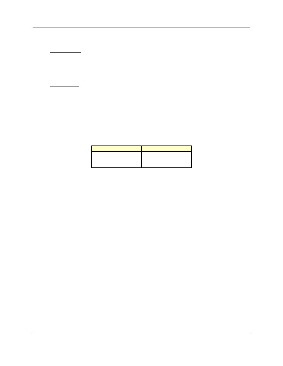
Some specifications for the terminating resistor are:
Table 4-7 Terminating Resistors
DeviceNet
SDS
121 ohm
120 ohm
1% metal film
2%
1/4 watt
1/4 watt
Important
: Per the DeviceNet and SDS specs -- do not terminate devices on drop lines.
An appropriate terminating resistor kit, WRC part number RM121DN, which satisfies both
DeviceNet and SDS specs, is included with your Extender.
Note
: The WRC-CANX Series 4 family is configured at the factory with 2 internal terminating
resistors
on each network – one for Network A and one for Network B – using jumpers W1 and W3. If
these are used in a trunk line, no other terminators should be placed at the CANX that end of the network.
Note
: If the CANX is used on a drop line, the internal terminating resistor should be removed on
Network A – the drop line directly from the trunk line.