Parts identification – Sony ICD-PX470 Digital Voice Recorder with USB User Manual
Page 4
4
Parts Identification
a
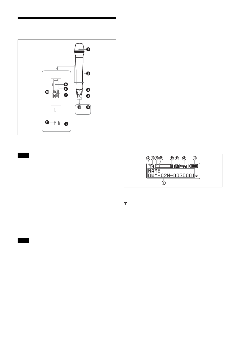
Microphone capsule unit (not supplied)
Mount the microphone capsule unit securely.
Make sure that the wireless microphone is turned off
before mounting or removing the microphone capsule unit.
Mounting or removing the unit while the wireless
microphone is turned on may result in malfunctions.
For details on mounting, refer to the operating
instructions supplied with your microphone capsule unit.
b
Grip
Contains operation buttons, display section, and the
battery holder.
Open the grip to make settings or install the batteries.
For details on how to open the grip, see “Installing the
Batteries” on page 5.
When the grip is open, the metal part of the grip obstructs
the antenna for RF transmission and wireless remote
control system. To transmit the signal or to use the wireless
remote control function with this microphone, be sure to
close the grip.
c
Identification ring
The ring can be replaced with the ones supplied.
This is useful when multiple microphones are used in the
system.
For details on how to replace the identification ring, see
“Replacing the Identification Ring” on page 6.
d
Antenna cover
Holds the antenna for RF transmission and wireless remote
control function.
e
POWER indicator
Lights up green when the microphone is turned on. When
the battery is exhausted, the indicator starts flashing.
f
USB connector (Micro USB)
Use this connector to connect an optional USB keyboard to
carry out menu functions using key operations.
By connecting the digital wireless receiver to this
connector using a USB cable (not supplied) and the USB
adapter cable (supplied), you can exchange the encryption
key for encrypted transmission function.
g
+ or – button
Selects functions or values shown on the display.
Holding down the – button while switching on the
microphone activates the pairing operation for the wireless
remote control function.
h
SET button
Adjusts displayed function settings and enters the value.
Holding down the SET button while switching on the
power turns the microphone on without sending a signal.
i
Display section
A
RF transmission indication
Indicates the current transmission status.
:
Currently transmitting
—:
Transmission stopped
B
RF (radio frequency) transmission power
indication
Indicates the current transmission power setting. You can
change the setting with the RF transmission power setting
function.
H:
transmitting at 50 mW
M:
transmitting at 10 mW
L:
transmitting at 1 mW
C
Audio input level meter
Indicates the signal input level.
D
Reference level gauge
Indicates the reference input level. When the attenuation is
0 dB, 94 dBSPL is indicated.
E
Peak indicator
Warns of excessive input by lighting up when the signal is
3 dB below the level at which distortion begins.
Note
Note
Inside the
grip
Front
Side
Bottom of
the antenna
cover
DWM-02N-0030001