Connection, 4english, Antenna connection – Panasonic TYFB9TU User Manual
Page 4: Installation
4
English
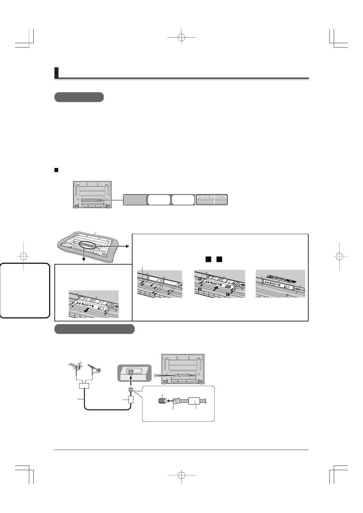
Antenna Connection
VHF Antenna UHF Antenna
75
Ω
Coaxial
Cable
Ferrite core
(included)
Ferrite core
(included)
F-type antenna
adapter (included)
Note
• To obtain optimum quality picture and
sound, an Antenna, the correct cable
( 7 5
Ω
c o a x i a l ) a n d t h e c o r r e c t
terminating plug are required.
• If a communal Antenna system is used,
you may require the correct connection
cable and plug between the wall Antenna
socket and your television receiver.
• Your local television service center or
dealer may be able to assist you in
obtaining the correct Antenna system for
your particular area and the accessories
required.
• Any matters regarding Antenna installation,
u p g r a d i n g o f e x i s t i n g s y s t e m s o r
accessories required, and the costs
incurred, are your responsibility.
For proper reception of VHF/UHF channels, an external antenna is required. For best reception, an outdoor antenna
is recommended. The antenna mode must be set to “TV” (see page 11, SET UP menu-MODE).
Connection
1.Remove the
slot cover.
2.Insert the terminal board
until it is firmly plugged
into the connector.
Tighten screws in the
order
1
-
4
.
3.Affix the terminal
function label
(included).
To install
75
Ω
VHF/UHF
Remove the slot cover. Grip the
handle of the terminal board, and
slowly pull out in the direction of
the arrow.
To remove
• Make sure that the Board does not ride on the two lower claws.
• Be sure to fasten all screws tightly.
• Have the customer keep the removed Terminal Board for future servicing needs.
Mixer
Securing screw
MATE
Compatible slot Nos. are SLOT2 and SLOT3.
Precautions
• Before installation
Turn the power switch off and disconnect the plug of the display.
Disconnect all the plugs connected to the display.
• Before removing, turn the power off with the tuner board’s remote control and then turn the main power off.
• When installing or removing the terminal board, exercise care to avoid injury.
There may be some sharp-pointed solder joints on the rear side of the board that could cause unexpected injury.
• When installing the board, fully insert the Board into the slot horizontally until it is firmly plugged into the
connector.
Note that incomplete insertion may damage the internal components.
Foam mat or thick soft cloth
SERIAL
PC IN
AUDIO
Installation
SLOT3
3 slots model
SLOT1
SLOT2