Assembly – Ryobi BTS20R-1 User Manual
Page 18
Page 18
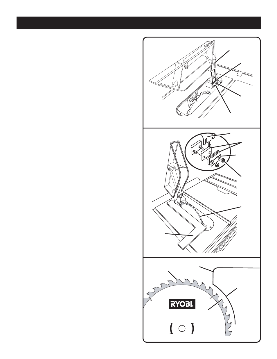
TO INSTALL BLADE GUARD ASSEMBLY
See Figure 13.
Lower the blade by turning the height adjusting handwheel
clockwise.
� Using the small wrench, install the blade guard assembly
by loosening the two hex nuts enough to slide the spreader
down between the shims. Partially retighten the two nuts.
Make sure the spreader clears the blade by 1/8 in.
� Correctly align the blade and spreader, as described
below. Tighten nuts securely when properly aligned.
TO CHECK, REPLACE OR ADJUST THE BLADE
GUARD ASSEMBLY
See Figures 14 - 15.
Proper installation of the blade guard assembly means that
the saw blade and spreader are in alignment. ALWAYS align
the spreader to the saw blade prior to turning on the table
saw.
The spreader is mounted between several shims that can be
relocated as needed to center the blade. It is held in place
by two bolts and hex nuts at its base. The bolts are set in
slots that permit front-to-back adjustment.
To check alignment of the spreader:
Unplug the saw, lower the blade, and remove the throat
plate.
Make sure the bevel locking lever is securely pushed to
the left. Raise the blade by turning the height adjusting
handwheel counterclockwise.
Lift the anti-kickback pawls and place a framing square
against both the saw blade and spreader.
The saw blade and spreader are aligned when the framing
square contacts both the blade and spreader evenly with
no gaps.
If the spreader and saw blade are not in alignment,
adjustment is needed. To adjust:
Unplug the saw, lower the blade, and remove the throat
plate.
With the box end of the small wrench, remove the two
nuts at the base of the spreader. Remove the blade guard
assembly.
Move the shims to bring the spreader into alignment
with the saw blade. Reinstall the spreader between the
shims.
NOTE: It may be necessary to remove the shims and turn
them in an opposite direction.
Recheck the alignment by placing the framing square
beside the saw blade as explained above.
Bring the blade back to the desired angle and height.
Lower the blade, insert the throat plate, then securely
tighten the throat plate screw.
NOTE: Anti-kickback pawls must be above the spreader
before tightening the throat plate screws.
Fig. 13
ASSEMBLY
SHIMS
MOUNTING PLATE
SPREADER
DO NOT REMOVE HEX NUTS
HEX
NUTS
Fig. 15
BLADE
1/8 in.
Fig. 14
MOUNTING
PLATE
HEX
NUTS
SHIMS
SPREADER
SPREADER
FRAMING
SQUARE
BLADE