Operation – Ryobi BTS20R-1 User Manual
Page 21
Page 21
OPERATION
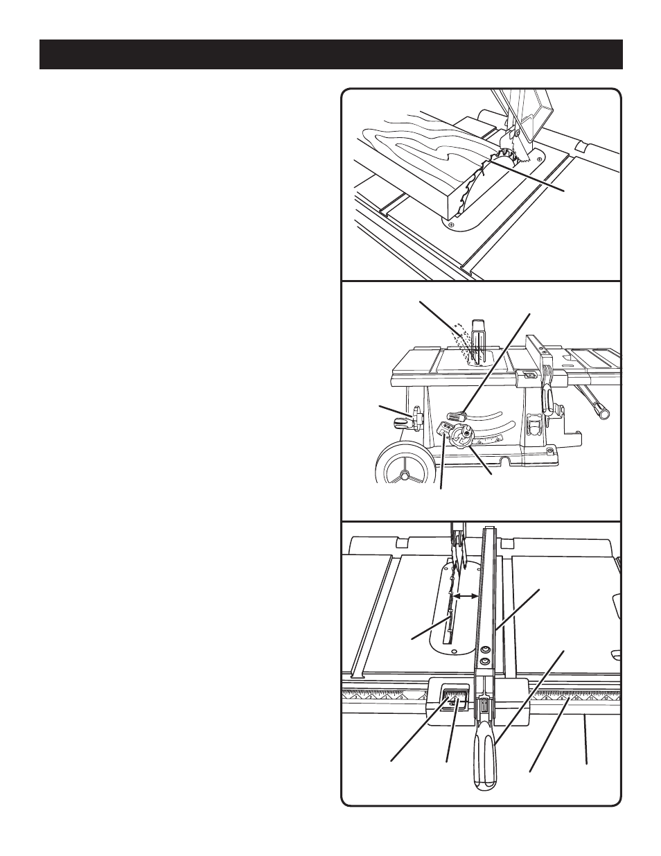
TO CHANGE BLADE DEPTH
See Figure 18.
The blade depth should be set so that the outer points of
the blade are higher than the workpiece by approximately
1/8 in. to 1/4 in. but the lowest points (gullets) are below
the top surface.
Push the bevel locking lever to the left for elevation
mode.
Raise the blade by turning the height adjusting handwheel
counterclockwise or lower it by turning the handle
clockwise.
TO CHANGE BLADE ANGLE
See Figure 19.
Unlock the bevel locking lever.
Angle the blade by turning the bevel handwheel until the
bevel indicator shows the correct angle.
Lock the bevel locking lever securely while holding the
bevel handwheel in place.
TO SET THE RIP FENCE SCALE INDICATOR
TO THE BLADE
See Figure 20.
The scale is usable from 0-27 in. (0-686 mm) to the right side
of the blade and 0-6 3/4 in. (0-171 mm) on the left side of
the blade. The operator can select any desired dimension
within those ranges. Use the following steps to set the scale
to the blade and scale indicator. Begin with the blade at a
zero angle (straight up).
Loosen the rip fence by raising the locking handle.
Using a framing square, set the rip fence 2 in. from the
blade tip edge.
Loosen the screw on the scale indicator.
Align the scale indicator to the 2 in. mark.
Tighten the screw and check the dimension and the rip
fence.
GULLET
Fig. 18
BEVEL
INDICATOR
BEVEL
LOCKING LEVER
BEVEL
HANDWHEEL
Fig. 19
ANGLED BLADE
HEIGHT
ADJUSTING
HANDWHEEL
Fig. 20
FRONT RAIL
2 in.
LOCKING
HANDLE
BLADE
RIP
FENCE
2 in.
MARK
SCALE
SCALE
INDICATOR