2 integrated protection mechanisms, 3 reaction times, Integrated protection mechanisms – Pilz PSSu E S 4DI-D User Manual
Page 13: Reaction times
Function description
Operating Manual PSSu E S 4DI-D
1001322-EN-04
13
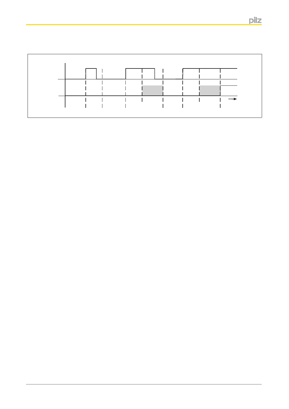
Timing diagram
Input
PII
t
2
+t
3
t
t
1
t
1
t
2
+t
3
t
1
}
Input: Signal at the input
}
PII: Status of process image (PII)
}
t
1
Minimum processing time (see Technical details)
}
t
2
Maximum processing time (see Technical details)
}
t
3
Cycle time of module bus
Shaded area: Status of process image (PII) undefined.
Integrated protection mechanisms
When the PSSu E F PS1(-T) is used to supply the system, the module supply is buffered
for 20 ms if the supply voltage is interrupted.
The module provides the following diagnostic data:
}
Start-up error
}
Configuration error
}
ST communication error
}
Bus termination error
}
Output overload
}
Temperature error: too warm
}
Temperature error: too hot
Reaction times
Information on the reaction times of the inputs can be found in the PSSuniversal System
Description.
4.1.2
4.1.3