Front view, Overview – Pilz PSS67 F 16DI SB-T User Manual
Page 12
Advertising
Overview
2 - 2
Operating Manual: PSS67 F 16DI SB-T
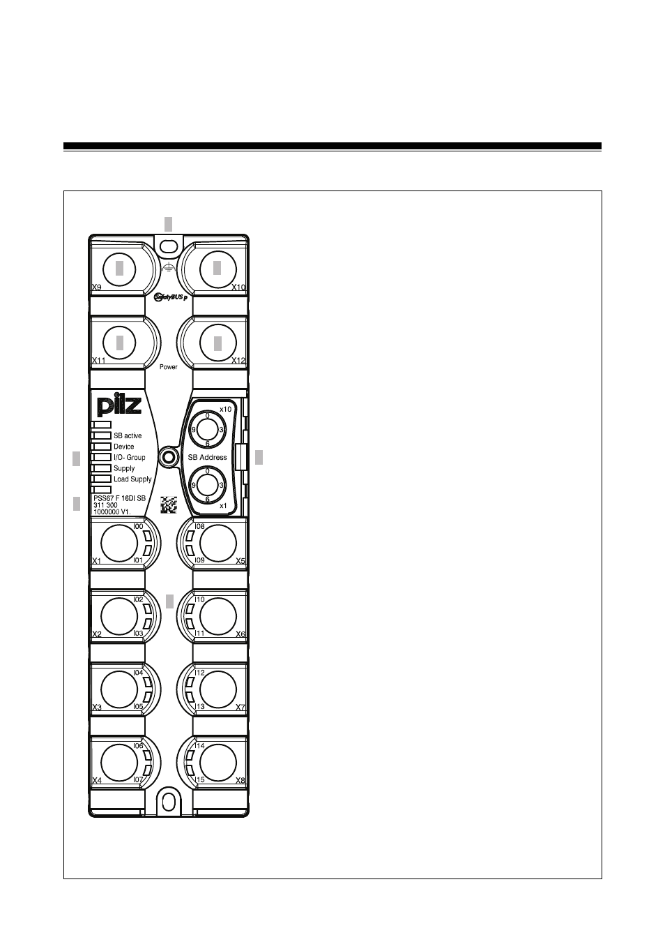
1: SafetyBUS p IN interface X9 (M12 male
connector)
2: SafetyBUS p OUT interface X10 (M12 female
connector)
3: Supply voltage connection IN
X11 (M12 male connector)
4: Supply voltage connection OUT
X12 (M12 female connector)
5: LEDs for operating status and
voltage supply
6: Rotary switch for setting the device address
on SafetyBUS p
7: Plug-in connectors for inputs and
test pulse outputs X1 to X8 (M12 female
connectors)
8: Functional earth connection
9: Labelling strip with:
• Device type
• Order number
• Serial number/hardware version
Fig. 2-1: Front view
Front view
3
1
2
4
5
6
8
7
1
9
Advertising
See also other documents in the category Pilz Sensors:
- PSEN in1p (16 pages)
- PSEN in1n (12 pages)
- PSEN rs2.0-300 (16 pages)
- PSEN rs1.0-175 (16 pages)
- PSEN enc m1 eCAM (46 pages)
- PSENme 1S / 1AS (16 pages)
- PSENme 1S / 1AS (6 pages)
- PSENme 2 / 2A (6 pages)
- PSENme 4 / 4A (5 pages)
- PSEN 1.2p-23/PSEN 1.2-20/8mm/ATEX/ 1unit (8 pages)
- PSEN 1.1a-20/PSEN 1.1-20 /8mm/5m/1unit (6 pages)
- PSEN 1.2p-25/PSEN 1.2-20/8mm/ATEX/ix1 (8 pages)
- PSEN 1.1a-22/PSEN 1.1-20 /8mm/5m/ix1/1un (6 pages)
- PNOZ m EF 2MM (6 pages)
- PSEN 1.1b-23/PSEN1.1-20/8mm/10m/EX/1unit (8 pages)
- PNOZ m EF 2MM (6 pages)
- PSEN 1.1p-20/PSEN 1.1-20/8mm/ 1unit (6 pages)
- PSEN 1.1p-29/PSEN 1.1-20/7mm/ix1/ 1unit (6 pages)
- PSEN 1.1b-25/PSEN1.1-20/8mm/10m/EX/1unit (8 pages)
- PNOZ m EF 2MM (8 pages)
- PSEN 1.1p-22/PSEN 1.1-20/8mm/ix1/ 1unit (6 pages)
- PSEN 1.1-10 / 1 actuator (6 pages)
- PSEN 1.2p-20/PSEN 1.2-20/8mm/ 1unit (6 pages)
- PSEN 1.1p-23/PSEN 1.1-20/8mm/ATEX/ 1unit (8 pages)
- PNOZ m EF 2MM (6 pages)
- PSEN 1.2p-22/PSEN 1.2-20/8mm/ix1/ 1unit (6 pages)
- PSEN 1.1p-25/PSEN 1.1-20/8mm/ATEX/ix1 (8 pages)
- PSEN 1.1-10 / 1 actuator (6 pages)
- PSEN ma1.3a-20/PSEN ma1.3-08/8mm/1unit (10 pages)
- PSEN ma1.3a-22/PSEN ma1.3-08/8mm/1unit (10 pages)
- PSEN ma1.3b-23/PSEN ma1.3-08/8mm/1unit (10 pages)
- PSEN ma1.3b-25/PSEN ma1.3-08/8mm/1unit (10 pages)
- PSEN ma1.3p-20/PSEN ma1.3-08/8mm/1unit (10 pages)
- PSEN ma1.3p-22/PSEN ma1.3-08/8mm/ix1/1un (10 pages)
- PSEN ma1.3n-20/PSEN ma1.3-08/8mm/1unit (12 pages)
- PSEN ma1.3-20 M12/8-0.15m 1switch (10 pages)
- PSEN ma1.4p-52/PSEN ma1.4-03mm/ 1unit (10 pages)
- PSEN ma1.4p-51/PSEN ma1.4-03mm/ 1unit (10 pages)
- PSEN ma1.4n-51/ 1switch (9 pages)
- PSEN ma1.4n-50/PSEN ma1.4-03mm/ 1unit (10 pages)
- PSEN ma1.4-51 M12/8-0.15m 1switch (10 pages)
- PSEN ma1.4p-57/PSEN ma1.4-10mm/ 1unit (10 pages)
- PSEN ma1.4a-52/PSEN ma1.4-03mm/ 1unit (10 pages)
- PSEN ma1.4a-51/PSEN ma1.4-10mm/ 1unit (10 pages)
- PSEN ma1.4p-50/PSEN ma1.4-03mm/ 1unit (10 pages)