General, Terminal box on servo motors ac1 and ac2, Wiring – Pilz Cable PMCprimoDrive>Mod-Profibus:L=0,45m User Manual
Page 32
Wiring
7-6
Operating Manual: PMCtendo AC
Connections for supply voltage, thermal switch and holding brake
General
If you are using a cable that incorporates the wires for the holding brake, the wires for
the holding brake must be shielded.
Terminal box on servo motors AC1 and AC2
To supply the voltage to the servo motor (see Fig. 7-7) via the servo amplifier you will
need a cable with a layout as shown in Fig. 7-8.
INFORMATION
The thermal switch is dual wired. It is carried in the motor feedback cable (see sections
entitled “Resolver” and “Hiperface rotary encoder”), as well as the supply voltage cable.
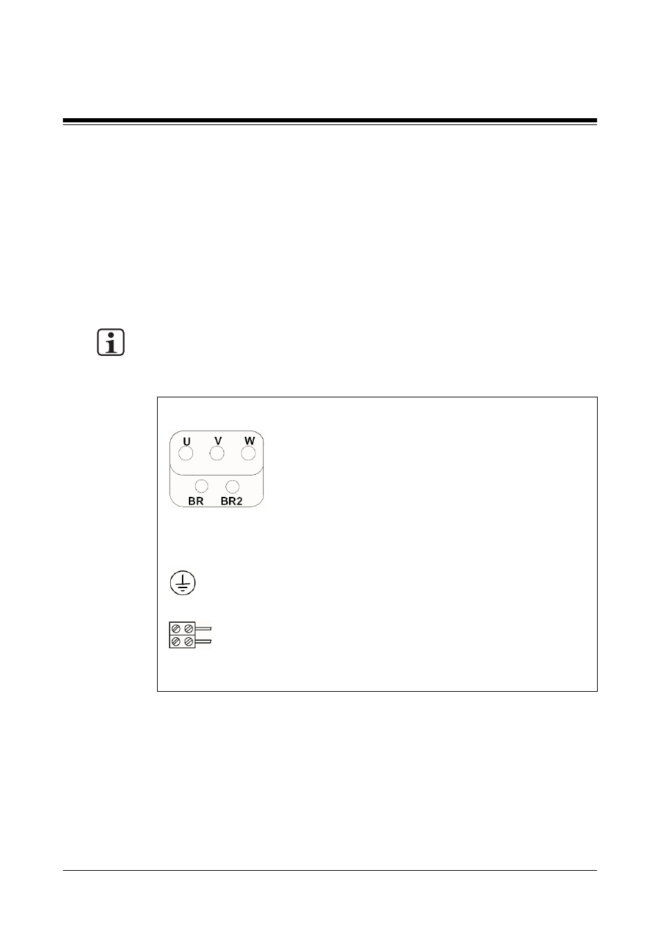
Fig. 7-7: Pin assignment within the terminal box (servo motors AC1 and AC2)
Connection terminals
Supply voltage for servo motor:
U:
Phase U
V:
Phase V
W:
Phase W
Thermal switch:
BR:
Thermal switch
BR2: Thermal switch
PE:
Earth connector
Holding brake (optional):
Red: + 24 VDC
Blue: 0 V
- Cable Resolver DD4plug>ACplug:L10mSK Cable Resolver DD4plug>ACplug:L05mSK Cable Hiperface DD4plug>ACplug:L05m Cable Power DD4plug>ACbox:L05mQ1,5BrSK Cable Power DD4plug>ACbox:L10mQ1,5BrSK Cable Power DD4plug>ACplug1:L05mQ1,5BrSK Cable Resolver DD4plug>ACplug:L15mSK Cable Power DD4plug>ACbox:L15mQ1,5BrSK Cable Power DD4plug>ACbox:L20mQ1,5BrSK PMCtendo AC2.62/0/5/1/2/5/H/3 PMCtendo AC2.74/0/5/1/1/4/H/2 PMCtendo AC2.62/1/M/1/2/5/H/3 PMCtendo AC2.64/1/5/1/2/5/H/3 PMCtendo AC2.73/0/5/1/2/5/H/3 PMCtendo AC2.73/1/M/1/2/5/H/4 PMCtendo AC2.62/0/L/1/2/5/H/3 PMCtendo AC2.63/1/M/1/2/5/H/3 PMCtendo AC2.73/1/5/1/2/5/H/3 PMCtendo AC2.63/0/L/1/2/5/H/3 PMCtendo AC2.65/0/5/1/2/5/H/3 PMCtendo AC2.65/0/L/1/2/5/H/3 PMCtendo AC2.75/0/L/1/2/5/H/3 PMCtendo AC2.72/0/5/1/2/5/H/3 PMCtendo AC2.74/0/M/1/2/5/H/3 PMCtendo AC2.75/0/M/1/2/5/H/3 PMCtendo AC3.35/0/5/1/1/4/H/3 PMCtendo AC2.62/1/5/1/2/5/H/3 PMCtendo AC2.76/0/5/1/2/5/H/3 PMCtendo AC2.75/1/5/1/2/5/H/4 PMCtendo AC2.74/1/5/1/2/5/H/3 PMCtendo AC3.34/0/L/1/1/4/H/6 PMCtendo AC2.73/1/5/1/2/6/H/3 PMCtendo AC2.63/0/5/1/2/5/H/6 PMCtendo AC2.74/0/L/1/2/5/H/4 PMCtendo AC1.A4/0/L/1/2/5/H/2 PMCtendo AC2.63/0/5/1/2/5/H/3 PMCtendo AC3.31/0/M/1/1/4/H/6 PMCtendo AC3.32/0/5/1/1/4/H/6 PMCtendo AC3.32/0/M/1/1/4/H/6 PMCtendo AC3.31/0/5/1/1/4/H/6 PMCtendo AC3.34/0/5/1/1/4/H/3 PMCtendo AC2.62/0/L/1/2/5/H/6 PMCtendo AC4.62/0/5/1/6/6/H/3 PMCtendo AC3.32/0/5/1/1/4/H/3 PMCtendo AC3.32/0/L/1/1/4/H/6 PMCtendo AC3.31/0/L/1/1/4/H/3 PMCtendo AC2.74/0/L/1/2/6/H/4 PMCtendo AC3.34/0/L/1/6/5/H/3 PMCTENDO AC3.33/0/M/1/1/4/H/3 PMCtendo AC1.A4/0/M/1/1/4/H/3 PMCtendo AC2.72/0/M/1/1/4/H/3 PMCtendo AC4.62/0/5/1/1/4/H/3 PMCtendo AC2.62/0/5/1/1/4/H/3 PMCtendo AC2.62/1/5/1/1/4/H/3 PMCtendo AC2.62/1/M/1/1/4/H/3 PMCtendo AC2.64/0/5/1/1/4/H/3 PMCtendo AC2.64/0/M/1/1/4/H/3 PMCtendo AC2.64/1/5/1/1/4/H/3 PMCtendo AC2.73/0/5/1/1/4/H/3 PMCtendo AC2.73/1/5/1/1/4/H/3 PMCtendo AC2.74/0/5/1/1/4/H/3 PMCtendo AC2.74/1/5/1/1/4/H/3 PMCtendo AC2.76/0/5/1/1/4/H/3 PMCtendo AC3.34/0/M/1/1/4/H/3 PMCtendo AC2.65/1/M/1/1/4/H/3 PMCtendo AC2.75/1/M/1/1/4/H/4 PMCtendo AC2.63/0/5/1/6/6/H/3 PMCtendo AC2.62/0/M/1/1/4/H/3 PMCtendo AC4.63/0/L/1/6/5/H/3 PMCtendo AC1.A7/1/5/1/2/5/H/2 PMCtendo AC2.64/0/L/1/2/5/H/4 PMCtendo AC1.A5/0/5/1/1/4/H/3 PMCtendo AC3.32/1/M/1/1/4/H/6 PMCtendo AC2.53/0/5/1/1/4/H/3 PMCtendo AC3.32/1/5/1/1/4/H/6 PMCtendo AC2.73/1/M/1/1/4/H/3 PMCtendo AC3.35/1/5/1/1/4/H/3 PMCtendo AC2.76/0/L/1/6/5/H/2 PMCtendo AC4.65/0/L/1/6/5/H/3 PMCtendo AC2.77/0/M/1/1/4/H/3 PMCtendo AC1.A9/1/5/1/2/6/H/2 PMCtendo AC2.65/1/5/1/1/4/H/3 PMCtendo AC2.53/1/5/1/1/4/H/3 PMCtendo AC2.64/0/5/1/6/6/H/3 PMCtendo AC4.75/0/L/1/6/5/H/2 PMCtendo AC1.A4/0/L/1/2/5/H/3 PMCtendo AC4.65/0/M/1/6/6/H/6 PMCtendo AC1.A9/1/5/1/2/6/H/3 PMCtendo AC4.62/1/M/2/6/6/H/3 PMCtendo AC1.B2/0/L/1/6/6/H/3 PMCtendo AC2.53/1/5/1/6/6/H/3 PMCtendo AC2.65/1/M/1/6/6/H/3 PMCtendo AC3.35/1/5/1/6/6/H/3 PMCtendo AC2.62/1/M/2/6/6/H/3 PMCtendo AC3.32/0/M/2/6/5/H/6 PMCtendo AC3.32/0/M/2/6/6/H/6 PMCtendo AC2.76/0/L/1/1/4/H/3 PMCtendo AC2.54/0/5/1/1/4/H/3 PMCtendo AC1.A5/0/L/1/6/6/H/3 PMCtendo AC1.B4/1/5/1/6/5/H/A PMCtendo AC2.54/0/L/1/1/4/H/3 PMCtendo AC4.64/0/L/1/6/5/H/3 PMCtendo AC2.75/0/L/1/2/6/H/3 PMCtendo AC3.32/0/5/1/7/6/H/6 PMCtendo AC3.34/1/L/1/1/4/H/6 PMCtendo AC3.35/0/5/1/1/4/H/6 PMCtendo AC4.63/0/5/1/6/5/H/3 PMCtendo AC2.64/0/5/1/1/4/H/6 PMCtendo AC1.B2/0/5/1/6/6/H/3 PMCtendo AC4.62/1/M/2/6/6/H/D PMCtendo AC4.64/0/L/1/7/5/H/6 PMCtendo AC2.53/0/M/1/7/5/H/3 PMCtendo AC2.74/1/M/1/7/5/H/3 PMCtendo AC2.74/0/5/1/7/5/H/4 PMCtendo AC4.64/1/M/2/7/5/H/3 PMCtendo AC2.64/0/5/1/7/5/H/6 PMCtendo AC3.35/0/M/2/7/5/H/3 PMCtendo AC3.24/1/M/1/7/5/H/6 PMCtendo AC2.75/0/L/1/7/5/H/4 PMCtendo AC1.A5/0/L/2/7/5/H/2 PMCtendo AC1.A7/1/5/2/6/6/H/3 PMCtendo AC3.34/0/L/1/6/5/H/6 PMCtendo AC2.53/1/M/1/7/6/H/3 PMCtendo AC4.65/0/L/2/7/6/H/3 PMCtendo AC4.64/0/L/2/7/5/H/6 PMCtendo AC4.63/0/L/2/6/5/H/3 PMCtendo AC4.64/0/L/2/6/5/H/3 PMCtendo AC3.24/1/5/1/7/5/H/6 PMCtendo AC3.34/0/L/2/6/5/H/6