Terminal box on servo motors ac3 and ac4, Wiring – Pilz Cable PMCprimoDrive>Mod-Profibus:L=0,45m User Manual
Page 34
Wiring
7-8
Operating Manual: PMCtendo AC
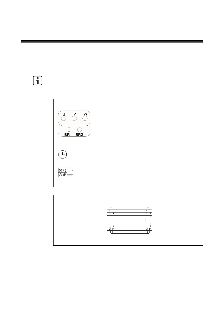
Terminal box on servo motors AC3 and AC4
To supply the voltage to the servo motor (see Fig. 7-9) via the servo amplifier you will
need a cable with a layout as shown in Fig. 7-10.
INFORMATION
Please note that the thermal switch connection is only available via the motor feedback
cable (see sections entitled “Resolver” and “Hiperface rotary encoder”).
Cable features:
• Cable cross section: max. 14 mm
- Wires for supply voltage: max. 3 x 2.5 mm
2
- Wire for earth conductor PE: max. 1 x 2.5 mm
2
- Wires for holding brake: max. 2 x 1 mm
2
• Cable runs:
- Depend on the requirements of the servo amplifier you are using
Fig. 7-10: Connection cable for the terminal box (servo motors AC3 and AC4)
Connection cable (servo motor)
Servo amplifier
Shield
1
3
4
PE
Phase U
Phase W
Phase V
Holding brake
+ 24 VDC
0 VDC
Earth conductor
Phase U
Phase W
Phase V
Holding brake
+ 24 VDC
0 VDC
Earth conductor
Fig. 7-9: Pin assignment within the terminal box (servo motors AC3 and AC4)
Connection terminals
Supply voltage for servo motor:
U:
Phase U
V:
Phase V
W:
Phase W
Thermal switch:
BR:
Not connected
BR2: Not connected
PE:
Earth conductor
Holding brake (optional):
Red: + 24 VDC
Blue: 0 V
- Cable Resolver DD4plug>ACplug:L10mSK Cable Resolver DD4plug>ACplug:L05mSK Cable Hiperface DD4plug>ACplug:L05m Cable Power DD4plug>ACbox:L05mQ1,5BrSK Cable Power DD4plug>ACbox:L10mQ1,5BrSK Cable Power DD4plug>ACplug1:L05mQ1,5BrSK Cable Resolver DD4plug>ACplug:L15mSK Cable Power DD4plug>ACbox:L15mQ1,5BrSK Cable Power DD4plug>ACbox:L20mQ1,5BrSK PMCtendo AC2.62/0/5/1/2/5/H/3 PMCtendo AC2.74/0/5/1/1/4/H/2 PMCtendo AC2.62/1/M/1/2/5/H/3 PMCtendo AC2.64/1/5/1/2/5/H/3 PMCtendo AC2.73/0/5/1/2/5/H/3 PMCtendo AC2.73/1/M/1/2/5/H/4 PMCtendo AC2.62/0/L/1/2/5/H/3 PMCtendo AC2.63/1/M/1/2/5/H/3 PMCtendo AC2.73/1/5/1/2/5/H/3 PMCtendo AC2.63/0/L/1/2/5/H/3 PMCtendo AC2.65/0/5/1/2/5/H/3 PMCtendo AC2.65/0/L/1/2/5/H/3 PMCtendo AC2.75/0/L/1/2/5/H/3 PMCtendo AC2.72/0/5/1/2/5/H/3 PMCtendo AC2.74/0/M/1/2/5/H/3 PMCtendo AC2.75/0/M/1/2/5/H/3 PMCtendo AC3.35/0/5/1/1/4/H/3 PMCtendo AC2.62/1/5/1/2/5/H/3 PMCtendo AC2.76/0/5/1/2/5/H/3 PMCtendo AC2.75/1/5/1/2/5/H/4 PMCtendo AC2.74/1/5/1/2/5/H/3 PMCtendo AC3.34/0/L/1/1/4/H/6 PMCtendo AC2.73/1/5/1/2/6/H/3 PMCtendo AC2.63/0/5/1/2/5/H/6 PMCtendo AC2.74/0/L/1/2/5/H/4 PMCtendo AC1.A4/0/L/1/2/5/H/2 PMCtendo AC2.63/0/5/1/2/5/H/3 PMCtendo AC3.31/0/M/1/1/4/H/6 PMCtendo AC3.32/0/5/1/1/4/H/6 PMCtendo AC3.32/0/M/1/1/4/H/6 PMCtendo AC3.31/0/5/1/1/4/H/6 PMCtendo AC3.34/0/5/1/1/4/H/3 PMCtendo AC2.62/0/L/1/2/5/H/6 PMCtendo AC4.62/0/5/1/6/6/H/3 PMCtendo AC3.32/0/5/1/1/4/H/3 PMCtendo AC3.32/0/L/1/1/4/H/6 PMCtendo AC3.31/0/L/1/1/4/H/3 PMCtendo AC2.74/0/L/1/2/6/H/4 PMCtendo AC3.34/0/L/1/6/5/H/3 PMCTENDO AC3.33/0/M/1/1/4/H/3 PMCtendo AC1.A4/0/M/1/1/4/H/3 PMCtendo AC2.72/0/M/1/1/4/H/3 PMCtendo AC4.62/0/5/1/1/4/H/3 PMCtendo AC2.62/0/5/1/1/4/H/3 PMCtendo AC2.62/1/5/1/1/4/H/3 PMCtendo AC2.62/1/M/1/1/4/H/3 PMCtendo AC2.64/0/5/1/1/4/H/3 PMCtendo AC2.64/0/M/1/1/4/H/3 PMCtendo AC2.64/1/5/1/1/4/H/3 PMCtendo AC2.73/0/5/1/1/4/H/3 PMCtendo AC2.73/1/5/1/1/4/H/3 PMCtendo AC2.74/0/5/1/1/4/H/3 PMCtendo AC2.74/1/5/1/1/4/H/3 PMCtendo AC2.76/0/5/1/1/4/H/3 PMCtendo AC3.34/0/M/1/1/4/H/3 PMCtendo AC2.65/1/M/1/1/4/H/3 PMCtendo AC2.75/1/M/1/1/4/H/4 PMCtendo AC2.63/0/5/1/6/6/H/3 PMCtendo AC2.62/0/M/1/1/4/H/3 PMCtendo AC4.63/0/L/1/6/5/H/3 PMCtendo AC1.A7/1/5/1/2/5/H/2 PMCtendo AC2.64/0/L/1/2/5/H/4 PMCtendo AC1.A5/0/5/1/1/4/H/3 PMCtendo AC3.32/1/M/1/1/4/H/6 PMCtendo AC2.53/0/5/1/1/4/H/3 PMCtendo AC3.32/1/5/1/1/4/H/6 PMCtendo AC2.73/1/M/1/1/4/H/3 PMCtendo AC3.35/1/5/1/1/4/H/3 PMCtendo AC2.76/0/L/1/6/5/H/2 PMCtendo AC4.65/0/L/1/6/5/H/3 PMCtendo AC2.77/0/M/1/1/4/H/3 PMCtendo AC1.A9/1/5/1/2/6/H/2 PMCtendo AC2.65/1/5/1/1/4/H/3 PMCtendo AC2.53/1/5/1/1/4/H/3 PMCtendo AC2.64/0/5/1/6/6/H/3 PMCtendo AC4.75/0/L/1/6/5/H/2 PMCtendo AC1.A4/0/L/1/2/5/H/3 PMCtendo AC4.65/0/M/1/6/6/H/6 PMCtendo AC1.A9/1/5/1/2/6/H/3 PMCtendo AC4.62/1/M/2/6/6/H/3 PMCtendo AC1.B2/0/L/1/6/6/H/3 PMCtendo AC2.53/1/5/1/6/6/H/3 PMCtendo AC2.65/1/M/1/6/6/H/3 PMCtendo AC3.35/1/5/1/6/6/H/3 PMCtendo AC2.62/1/M/2/6/6/H/3 PMCtendo AC3.32/0/M/2/6/5/H/6 PMCtendo AC3.32/0/M/2/6/6/H/6 PMCtendo AC2.76/0/L/1/1/4/H/3 PMCtendo AC2.54/0/5/1/1/4/H/3 PMCtendo AC1.A5/0/L/1/6/6/H/3 PMCtendo AC1.B4/1/5/1/6/5/H/A PMCtendo AC2.54/0/L/1/1/4/H/3 PMCtendo AC4.64/0/L/1/6/5/H/3 PMCtendo AC2.75/0/L/1/2/6/H/3 PMCtendo AC3.32/0/5/1/7/6/H/6 PMCtendo AC3.34/1/L/1/1/4/H/6 PMCtendo AC3.35/0/5/1/1/4/H/6 PMCtendo AC4.63/0/5/1/6/5/H/3 PMCtendo AC2.64/0/5/1/1/4/H/6 PMCtendo AC1.B2/0/5/1/6/6/H/3 PMCtendo AC4.62/1/M/2/6/6/H/D PMCtendo AC4.64/0/L/1/7/5/H/6 PMCtendo AC2.53/0/M/1/7/5/H/3 PMCtendo AC2.74/1/M/1/7/5/H/3 PMCtendo AC2.74/0/5/1/7/5/H/4 PMCtendo AC4.64/1/M/2/7/5/H/3 PMCtendo AC2.64/0/5/1/7/5/H/6 PMCtendo AC3.35/0/M/2/7/5/H/3 PMCtendo AC3.24/1/M/1/7/5/H/6 PMCtendo AC2.75/0/L/1/7/5/H/4 PMCtendo AC1.A5/0/L/2/7/5/H/2 PMCtendo AC1.A7/1/5/2/6/6/H/3 PMCtendo AC3.34/0/L/1/6/5/H/6 PMCtendo AC2.53/1/M/1/7/6/H/3 PMCtendo AC4.65/0/L/2/7/6/H/3 PMCtendo AC4.64/0/L/2/7/5/H/6 PMCtendo AC4.63/0/L/2/6/5/H/3 PMCtendo AC4.64/0/L/2/6/5/H/3 PMCtendo AC3.24/1/5/1/7/5/H/6 PMCtendo AC3.34/0/L/2/6/5/H/6