Introduction, Installation – Nexen LH 100 912119 User Manual
Page 4
4
FORM NO. L-20334-C-0404
INTRODUCTION
Nexen’s LH100 Line Follower Sensor optically detects register lines, patterns, and edges. The LH100 offers improved
detection capabilities, especially for yellow and light blue. Combining the LH100 with one of Nexen’s Web Guide
Controllers provides Line Follower Control (LFC) and Edge Position Control (EPC).
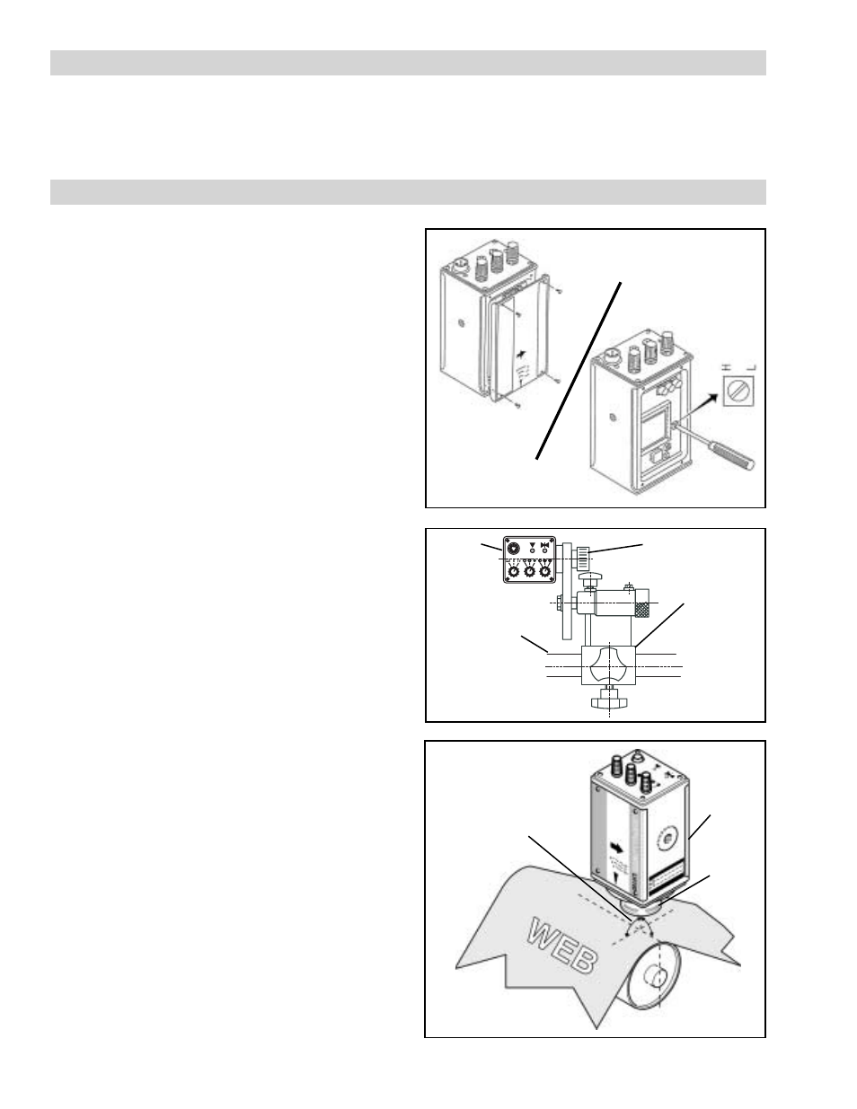
FIGURE 1
FIGURE 2
The LH100 has two output voltage ranges to meet the
requirements of different controllers:
High (H): 0–5 VDC
Low (L): 0–600 mVDC
The LH100 selector switch comes factory set to "L". To
ensure proper operation, set the LH100 sensor output
selector switch "H" or "L" according to the requirements
of the web guide controller you are using.
A
DJUSTING
THE
O
UTPUT
V
OLTAGE
S
ETTING
1.
Remove the selector switch cover to access the
High/Low switch (See Figure 1).
2.
Use a small, flat-blade screw driver to adjust the
High/Low switch to the desired setting. Turn the
switch until it comes to a stop on H or L.
OUTPUT VOLTAGE SETTINGS
INSTALLATION
1.
Secure the Mounting Bracket to a customer
supplied mounting bar (See Figure 2).
NOTE: The centerline of the LH100 must be perpendicular
(90
o
) to the web surface (See Figure 3).
2.
Secure the LH100 to the threaded extension of the
Screwguide mounted across the web path. Be sure
it is in a location where the web is supported from
beneath to prevent web flutter. (See Figure 3).
NOTE: Make sure the lock nut on the threaded extension
is tight against the LH100.
3.
Verify that the LH100 and Mounting Bracket are
both securely mounted to the mounting bar.
NOTE: If the web material is paper-like, non-shiny, and/
or rough, remove the Diffuser Cap by turning the cap
counterclockwise. Leave in place for reflective materials.
MOUNTING THE LH100
Mounting
Bracket
Screwguide
LH100
Mounting
Bar
FIGURE 3
The centerline of the
LH100 must be
perpendicular (90
o
) to
the web surface.
LH100
Diffuser
Cup