Indicators and switches – Nexen LH 100 912119 User Manual
Page 7
7
FORM NO. L-20334-C-0404
INDICATORS AND SWITCHES
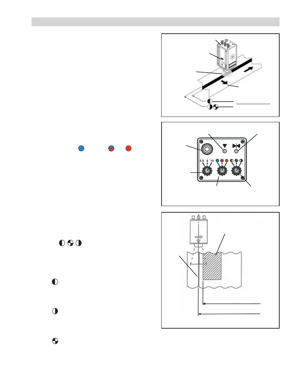
Focal
Display Indicator
Center
Display Indicator
Field of View
Selector
Switch
Color
Selector
Switch
Contrast
Selector
Switch
FIGURE 8
Cable
Connector
Receptacle
Line Follower Head
Scanning Direction
Indicator Arrow
Field of
View
Scanning
Direction
Detected Position
Detected Position
FIGURE 7
FIGURE 9
Edge position detected
better with blue light.
Edge position detected
better with red light.
Red Pattern
Blue Line
F
IELD
-
OF
-V
IEW
S
ELECTOR
S
WITCH
: used to select the desired
field of view width 2.5/5/10mm [.1/.2/.4 in]). 10mm
is the most common setting, 2.5 and 5mm are used
for restricted field-of-view area where patterns are
close together.
/Red
/Blue+Red
Blue
NOTE: Refer to Figure 7 for LH100 alignment on a web. Use
the Scanning Direction Indicator Arrow to determine the
direction of the LH100 scan. In Figure 7 the arrow is
pointed to the right, so the LH100 scans from left to right.
Refer to Figure 8 for the location of the indicator lights
and switches listed below.
INDICATORS:
C
ENTER
D
ISPLAY
I
NDICATOR
: illuminates when a web edge or
line edge is at the center of the LH100 view field.
F
OCAL
D
ISPLAY
I
NDICATOR
: illuminates when the mounting
distance and angle (90°) between the LH100 and
the web is correct and the web/line edge is within
the LH100 field-of-view.
SWITCHES:
C
OLOR
S
ELECTOR
S
WITCH
: used to select the color of the
light source (
Blue+Red is the most common.
NOTE: If an additional line or pattern of a different color
is within the LH100’s field of view (See Figure 9) the
LH100 may not be able to lock onto the proper edge. In
such a case, select the lamp color that most closely
matches the intruding line/pattern. This will make it more
difficult for the LH100 to see that color.
If the web or roller underneath a transparent web is less
reflective than the line or edge to be followed, select a
lamp color that is similar to the line or edge.
C
ONTRAST
S
ELECTOR
S
WITCH
: used to choose which edge of
the line to follow. There are three different mode
options:
NOTE: Look downstream of the web flow and use
the Scanning Direction Indicator Arrow to
determine the LH100 scanning direction. Select a
mode based on the descriptions below:
With selected, the LH100 scans in the direction
of the Arrow, looking for a change from dark to light
and follows that edge. In Figure 7 the right edge of
the line is detected as the control position.
With selected, the LH100 scans in the direction
of the Arrow, looking for a change from light to dark
and follows that edge. In Figure 7 the left edge of
the line is detected as the control position.
With selected, the LH100 scans in the direction
of the Arrow to detect the first contrast change. In
Figure 7 the left edge of the line is detected as the
control position. This is the most common setting.
).