Installation, System connection – Lenco APD-100 User Manual
Page 4
4
Installation
Before operate the MAP system, follow the setup that described in below system connection.
System Connection
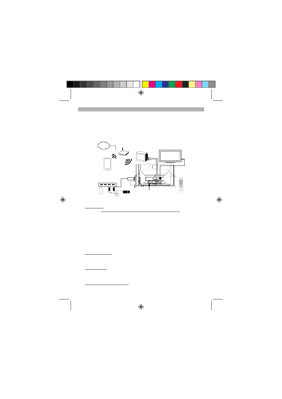
The following connections are the MAP system setup, see diagram A, to playback photo / music / video on a TV
set.
(A) It streams photo / music / video files from your Smart Phone through a Wi-Fi (wireless) network.
(B) The MAP Base playback photo / music / video files which stored in the USB / SD memory device.
(C) In tablet mode, you can access Internet through the Wi-Fi (wireless) network.
with Audio Signal Input and
Composite Video Input
(a)TV Set (Not Supplied)
(b) TV Set (Not Supplied)
with HDMI Input
Wi-Fi Router
Smart Phone
(Not Supplied)
To Power Adaptor
APD-100 MAP Base Unit
SD
Memory
Device
(Not Supplied)
USB
Memory
Device
(Not Supplied)
APD-100
Remote
Control
USB 2.0 Hub (Not Supplied)
Mouse
(Not Supplied)
Keyboard
(Not Supplied)
Internet
Diagram A : System Connection
1. Display
Device
Either, (a) For TV set (or other display device) with composite video input
Connect the RCA cable to the TV set and connect the other end of the cable (Left /
Right Audio channels and video) to the L / R / V RCA connectors located at rear of
the MAP Base unit.
Or,
(b) For TV set with HDMI input
Connect a HDMI cable to the HDMI input of the TV set and connect the other end
of the cable to the HDMI output located at rear of the MAP Base unit.
Note: If necessary, you may press the HDMI AUDIO ON/OFF button from the remote
control to mute the audio output from the digital TV set.
Note:
The MAP Base unit will either output HDMI signal or Composite Video signal one at a
time only (will not output both at the same time). You can select your desired video output
source from the remote control or from the on screen display (OSD) menu.
2.
Keyboard and Mouse
For easy operation of accessing Internet feature, connect a Keyboard and a mouse
(recommend using wireless type) to the USB port (USB 2.0) located at rear of the MAP unit,
see example in diagram A.
3. Wireless
Network
With a Wireless router paired the MAP Base unit and a Smart Phone.
Note: For Wi-Fi (wireless) setup, please read “Settings” section in this manual. To have
Internet operation, your Wi-Fi (wireless) router should be connected to the Internet network.
4.
AC-DC Power Adaptor Connection
The unit is powered by an external AC-DC power adaptor, required the output DC 12V
2000mA (included).
APD-100 5L IB.pdf 4
APD-100 5L IB.pdf 4
2012-5-31 14:46:12
2012-5-31 14:46:12