Toggle switch pin list, Displays, Leds – Altera Cyclone II FPGA Starter Development Board User Manual
Page 37: Led schematic, Displays –19
Altera Corporation
Reference Manual
2–19
October 2006
Cyclone II FPGA Starter Development Board
Development Board Components
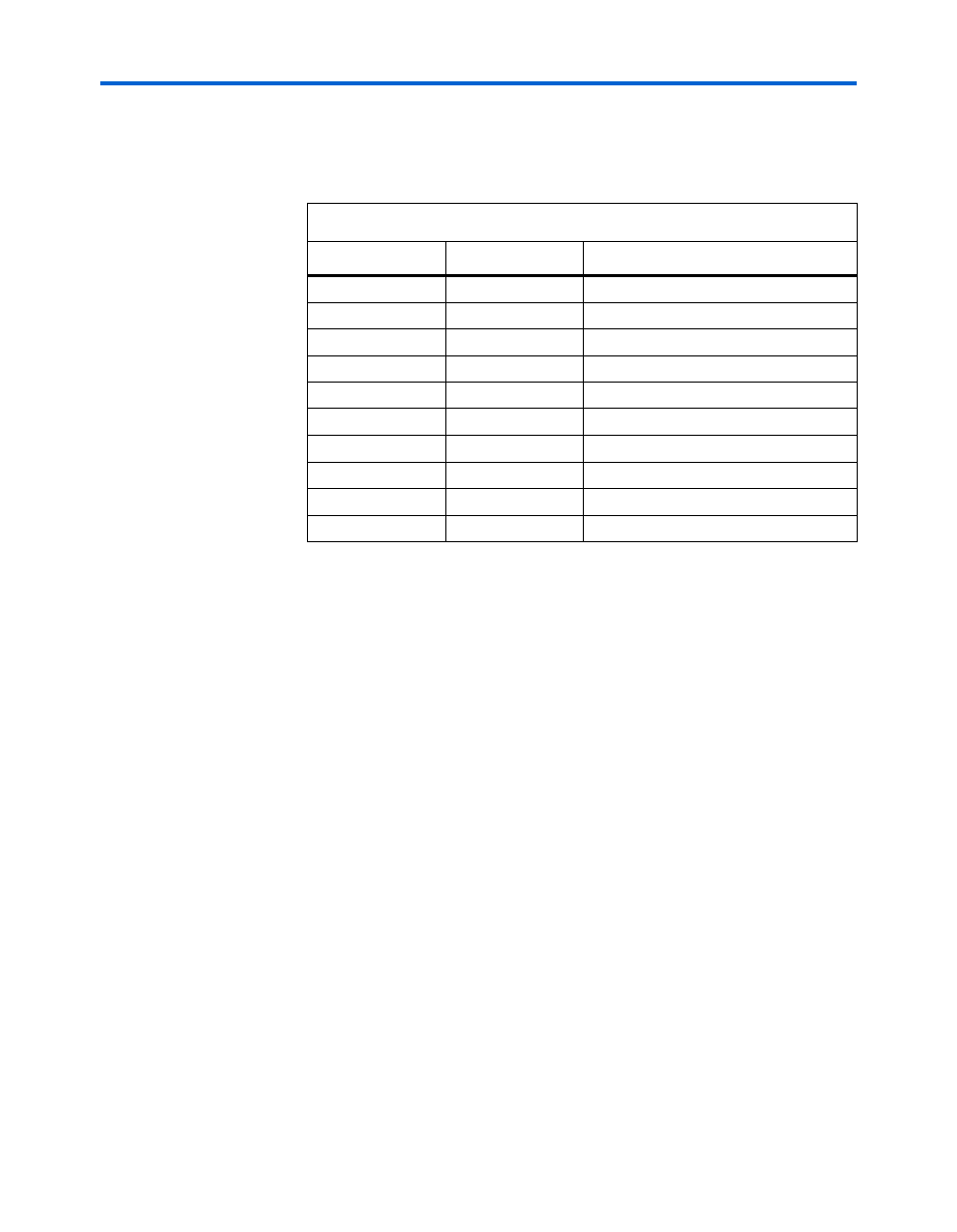
Toggle Switch Pin List
lists the FPGA pins assigned to the toggle switches.
Displays
The development board provides the following displays:
■
LEDs
■
Seven-segment displays
LEDs
The development board provides 18 user-controllable LEDs, 10 red LEDs,
LEDR0–LEDR9
, above the toggle switches (
) and 8 green
LEDs, LEDG0–LEDG7, above the four push button switches
(
). Each LED connects directly to an FPGA general purpose
I/O pin. A HIGH logic level on a pin turns the LED on; a LOW logic level
on a pin turns the LED off.
LED Schematic
shows a schematic diagram of the LEDs.
Table 2–11. Toggle Switch FPGA Pin Connections
Switch
FPGA Pin
Description
SW[0]
PIN_L22
Toggle Switch[0]
SW[1]
PIN_L21
Toggle Switch[1]
SW[2]
PIN_M22
Toggle Switch[2]
SW[3]
PIN_V12
Toggle Switch[3]
SW[4]
PIN_W12
Toggle Switch[4]
SW[5]
PIN_U12
Toggle Switch[5]
SW[6]
PIN_U11
Toggle Switch[6]
SW[7]
PIN_M2
Toggle Switch[7]
SW[8]
PIN_M1
Toggle Switch[8]
SW[9]
PIN_L2
Toggle Switch[9]