Act single channel wireless receiver – MIPRO act707se_ii(2ce158)c User Manual
Page 3
2
3
ACT SINGLE CHANNEL WIRELESS RECEIVER
ACT SINGLE CHANNEL WIRELESS RECEIVER
2. PARTS NAME AND FUNCTIONS
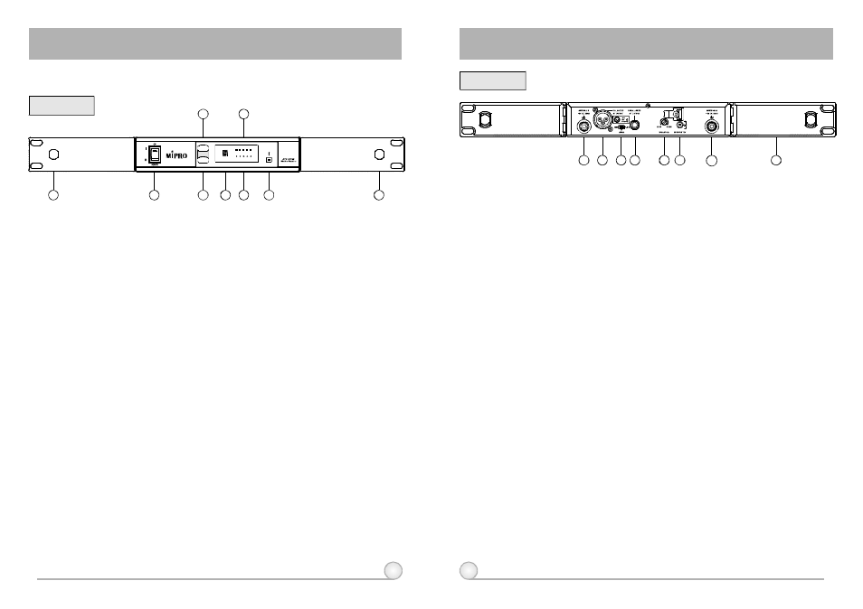
Front Panel:
Rear Panel:
(Fig.1)
(Fig.2)
(1)
Front Antenna A Input Connector : Allows an optional rear-to-front
Antenna kit for front antenna placement.
(2)
Power Switch & Indicator: When switch is turned on, red indicator
illuminates to denote normal power status.
(3)
ACT Button: To setup microphone frequency to match receiver frequency.
(4)
Scan Button: Press once to select receiving channel and autoscan the
whole bandwidth to avoid interference channel.
(5)
Channel Indicator: To display system's receiving channel.
(6)
RF Signal Level Indicator: Indicate the RF signal strength received.
(7)
Audio Signal Level Indicator: Indicate the audio signal level.
(8)
Noise Indicator: To display if the system is under interference.
(9)
Front Antenna B Input Connector : Allows an optional rear-to-front
Antenna kit for front antenna placement.
(10) Antenna B input Connector: Antenna B connector can be installed with
antenna directly and provides power for antenna booster.
(11) Balanced Audio Output Jack: With Cannon / XLR type connector provides
balanced audio output signal from this jack to the amplifier.
(12) Unbalanced Level Switch: "MIC" selection is for "Microphone-level" output.
"LINE" selection is for "Line-out" level output.
(13) Unbalanced Audio Output Jack: With 1/ 4
Phone Jack provides audio
output signal from this jack to the amplifier.
(14) Squelch Adjuster: Adjust the squelch level to eliminate the RF noise
interference at receiver stand-by state.
(15) DC Input Socket: The input socket for 12 Volt DC power. Please note
that the polarity of the central pin in the socket is positive (+).
(16) Antenna A Input Connector: Antenna A connector can be installed with
antenna directly and provides power for antenna booster.
(17) Rackmount Bracket: To install the receiver into an EIA 19-inch standard
rack case.
λ
Switch
between "LINE" and "MIC" for different purposes.
Switch between "LINE" and
"MIC" for different purposes.
NOISE
A F
R F
CHANNEL
N o .
1
2
5
6
8
4
7
9
S C A N
ACT
3
10
11
12 13
15
16
14
17