Applied Motion 1030 User Manual
Page 5
Connecting the Motor
Connecting the Power Supply
A+
A-
B+
B-
4
lead
motor
Red
Blue
Yellow
White
4 Leads
-12-
-5-
If you need information about choosing a power supply, please read
Choosing a
Power Supply located in the back of this manual.
If your power supply does not have a fuse on the output or some kind of short
circuit current limiting feature you need to put a 1 amp slow blow fuse between the
drive and power supply. Install the fuse on the positive power supply lead.
Connect the motor power supply positive (+) terminal to pin 2 of the power &
logic connector. Connect power supply return (-) to pin 1. Be careful not to
reverse the wires. Reverse connection will destroy your driver, void your
warranty and generally wreck your day.
About the voltage regulator
The 1030 requires 52 mA of power at 5 volts DC internally. We derive this 5V from
the DC power that you provide for the motor. This is a low cost and compact
technique, but does result in some heating of the voltage regulator.
Don't be surprised if the temperature of the regulator reaches 90˚C. This will not
affect the life of your drive, but if you accidentally touch the part, you won't be
happy.
You may add a heat sink to the voltage regulator if you wish. The metal tab is
electrically connected to ground (power supply "-").
Never use your drive in a space where there is no air flow or where the
air temperature is more than 70˚C. Never put the drive where it can
get wet or where metal particles can get on it.
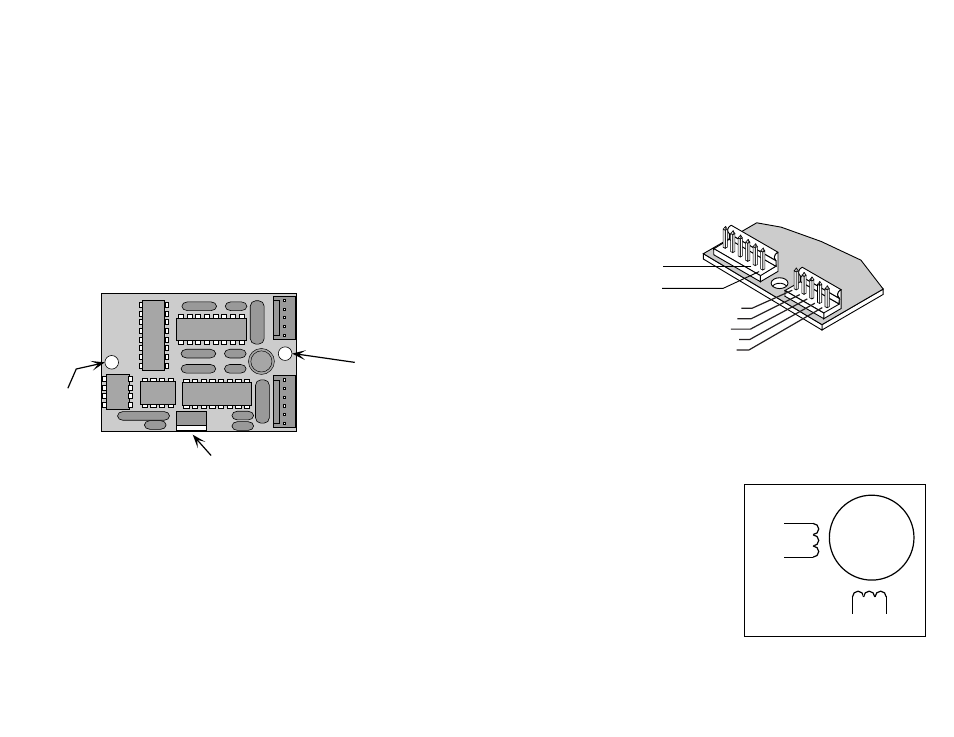
Mounting the Drive
The 1030 has two .156" holes in the circuit board for mounting. In the design of
this compact, low cost driver, it was necessary to route some circuit boards traces
fairly close to the mounting holes. Therefore, you must
only use plastic
standoffs or spacers to support the 1030.
You can drive #4 screws through the top of the board into a plastic spacer, but only
if you
put an insulating washer under the screw heads.
An excellent way to mount the 1030 in your application is to use two Richco model
LCBS-TF-6-01 spacers. The LCBS parts can be secured to your application with
#6-32 screws. The 1030 then snaps onto the LCBS spacers, and no metal is in
contact with the 1030. We use that configuration here at Applied Motion.
Richco makes a wide variety of innovative pcb mounting hardware. Their phone
number is 800-621-1892. Internet address is www.richcoplas.com.
mounting
hole
(.156")
mounting
hole
(.156")
voltage regulator
(Beware, this part gets HOT!!!)
Pin 2 (to power supply +)
Pin 1 (to power supply -)
Pin 5 (motor A+)
Pin 4 (motor A-)
Pin 3 (ground)
Pin 2 (motor B+)
Pin 1 (motor B-)
Note: if you are using a motor
with a shielded cable, connect
the drain wire to pin 3.
✔ When connecting the motor, be sure that the power supply is off.
✔ Isolate & secure any unused motor leads.
✔ Never disconnect the motor while the drive is powered up.
✔ Never connect motor leads to ground or to a power supply.
✔ Use a polarized mating connector.
You must now decide how to connect your
motor to the drive.
Four lead motors can only be connected
one way. Please follow the sketch at the
right.
Six lead motors can be connected in
series or center tap. In series mode,
motors produce more torque at low speeds,
but cannot run as fast as in the center tap
configuration. In series operation, the
motor should be operated at 30% less than the rated current to prevent overheating.
Wiring diagrams for both connection methods are shown on the next page.