Applied Motion 1030 User Manual
Page 6
A+
A-
B+
B-
8
lead
motor
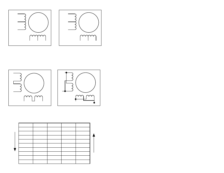
8 Leads Series Connected
Eight lead motors can also be connected in two ways: series and parallel. As
with six lead motors, series operation gives you more torque at low speeds and less
torque at high speeds. In series operation, the motor should be operated at 30%
less than the rated current to prevent over heating. The wiring diagrams for eight
lead motors are shown below.
A+
A-
NC
B+
B-
NC
6
lead
motor
Red
Black
Red/
Wht
Green
Grn/Wht
White
A+
A-
NC
B+
B-
NC
6
lead
motor
Grn/Wht
White
Green
Red
Red/
Wht
Black
6 Leads Series Connected
6 Leads Center Tap Connected
8 Leads Parallel Connected
A+
A-
B+
B-
8
lead
motor
-11-
-6-
Orange
Org/Wht
Blk/Wht
Black
Red
Red/
Wht
Yel/
Wht
Yellow
Orange
Org/
Wht
Blk/Wht
Black
Red
Red/Wht
Yel/
Wht
Yel
low
Step
A+
A-
B+
B-
0
-
+
0
0
1
-
+
-
+
2
0
0
-
+
3
+
-
-
+
4
+
-
0
0
5
+
-
+
-
6
0
0
+
-
7
-
+
+
-
8
-
+
0
0
DIR=0
ccw
DIR=1
cw
Step Table (half stepping)
Step 0 is the power up state
Choosing a Power Supply
Voltage
Chopper drives work by switching the voltage to the motor terminals on and off
while monitoring current to achieve a precise level of phase current. To do this
efficiently and silently, you’ll want to have a power supply with a voltage rating at
least five times that of the motor. Depending on how fast you want to run the motor,
you may need even more voltage than that. More is better, the only upper limit
being the maximum voltage rating of the drive itself: 30 volts. If you choose an
unregulated power supply, do not exceed 24 volts. This is because unregulated
supplies are rated at full load current. At lesser loads, like when the motor’s not
moving, the actual voltage can be up to 1.4 times the rated voltage.
Current
The maximum supply current you will need is the sum of the two phase
currents. However, you will generally need a lot less than that, depending on the
motor type, voltage, speed and load conditions. That's because the 1030 uses
switching amplifiers, converting a high voltage and low current into lower voltage
and higher current. The more the power supply voltage exceeds the motor voltage,
the less current you’ll need from the power supply.
We recommend the following selection procedure:
1. If you plan to use only a few drives, get a power supply with at least twice the
rated phase current of the motor.
2. If you are designing for mass production and must minimize cost, get one
power supply with more than two times the rated current of the motor . Install the
motor in the application and monitor the current coming out of the power supply
and into the drive at various motor loads. This will tell you how much current you
really need so you can design in a lower cost power supply.
If you plan to use a regulated power supply you may encounter a problem with
current foldback. When you first power up your drive, the full current of both motor
phases will be drawn for a few milliseconds while the stator fields are being
established. After that the amplifiers start chopping and much less current is drawn
from the power supply. If your power supply thinks this initial surge is a short
circuit it may “foldback” to a lower voltage. With many foldback schemes the
voltage returns to normal only after the first motor step and is fine thereafter. In that
sense, unregulated power supplies are better. They are also less expensive.
NC = not
connected
NC = not
connected