Applied Motion 3535 User Manual
Page 2
Features
Introduction
Thank you for selecting an Applied Motion Products motor control. We hope our
dedication to performance, quality and economy will make your motion control
project successful.
If there's anything we can do to improve our products or help you use them better,
please call or fax. We'd like to hear from you. Our phone number is (800) 525-
1609 or you can reach us by fax at (408) 761-6544.
Technical Specifications
Amplifiers
Oscillator
(O suffix)
Inputs
Physical
Connectors
CE Mark
Dual, bipolar H-bridge, pulse width modulated switching at 20
kHz. 12-35 VDC input. 0.4 - 3.5 amps/phase output current,
switch selectable in 0.1 A increments. 122 watts maximum output
power. Automatic idle current reduction, reduces current to 50%
of setting after one second.
400 to 5000 steps per second. Linear acceleration and
deceleration, individually adjustable from 5 to 900 msec.
Step, direction and enable, optically isolated, 5V logic. 5
mA/signal, sink requirement. Motor steps on rising edge of step
line. 10 µsec minimum low pulse. 50 µsec minimum set up time
for direction signal. Step input doubles as run/stop in oscillator
mode. (0 = run, 1 = stop.)
Mounted on 1/4 inch thick black anodized aluminum heat transfer
chassis. 1.5 x 3.0 x 4.0 inches overall. Power on LED. See
drawing on page 14 for more information. Maximum chassis
temperature: 70
°
C.
European style screw terminal blocks. Motor: 4 position. Signal
Input: 4 position. DC Input: 2 position.
-15-
-2-
Drives sizes 14 through 34 step motors
Pulse width modulation switching amplifiers
Phase current from 0.4 to 3.5 amps (switch selectable, 32 settings)
Step, direction and enable inputs, optically isolated
Full and half step (switch selectable)
Automatic 50% idle current reduction
Built in ramping pulse generator with adjustable speed, accel, decel (3535 O)
400 - 5000 Hz
•
•
•
•
•
•
•
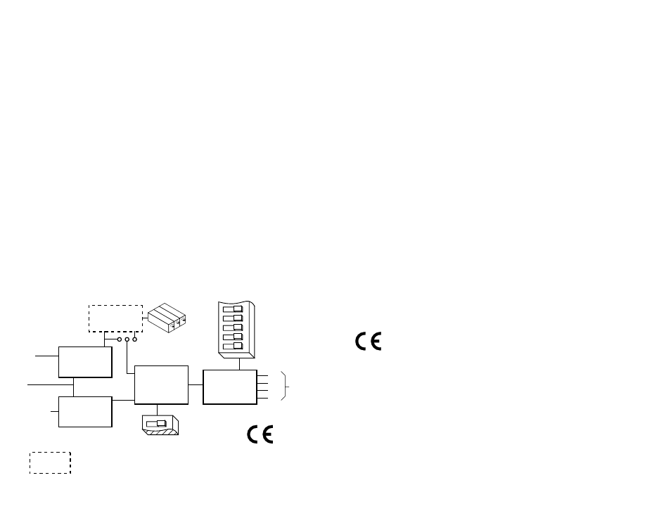
Amplifier
Optical
Isolator
step
direction
+5
1
Step
Sequencer
Optical
Isolator
Oscillator
STEP/SLEW JUMPER
current setting
full step/
half step
step
dir
accel
decel
speed adj
A+
A–
B+
B–
to
motor
Block Diagram
3535 O only
6
5
4
3
2
Complies with EN55011A and EN50082-1(1992).