Using the oscillator – Applied Motion 3535 User Manual
Page 8
Using the Oscillator
Drives with an O suffix are equipped with internal
pulse generators that you can use to drive the
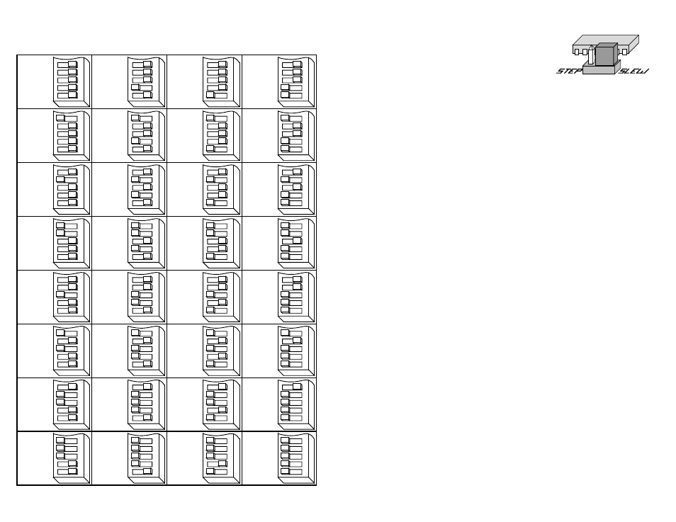
motor. To set the drive to oscillator mode, simply find the jumper located near the
center of the printed circuit board and move it to the SLEW setting. The figure at the
right shows the proper setting of the jumper.
The oscillator is activated by driving the
STEP input low. The frequency of step
pulses will increase linearly, accelerating the motor until it reaches a preset slew
speed. The motor will remain at this speed until the
STEP input is driven high. The
step pulse frequency then decreases linearly, decelerating the motor and load to
rest.
To change the slew speed, locate the trimpot labeled
SPEED. By turning the brass
screw you can raise or lower the speed within a range of 400 to 5000 steps per
second. Turning the screw clockwise makes the motor run faster.
The acceleration and deceleration rates can also be adjusted using the trimpots
labeled
ACCEL and DECEL. The range of accel and decel time is 5 to 900
milliseconds. Turning the screw clockwise makes the motor accelerate and
decelerate faster.
Using Remote Speed Control Potentiometer
The latest revision of model 3535 O step motor driver includes an analog signal
input connector that can be used to control the oscillator speed externally.
Normally, an on board potentiometer controls the speed.
To determine if your 3535 O is the correct revision: look for either a two pin header
labeled ÒXSPDÓ near the three blue trimpots or the name on the PC board 1000-053
followed by a letter B or C.
You will need:
• a 100k
Ω
or 200k
Ω
linear potentiometer. A multiturn type is recommended.
• a two pin female connector compatible with .025 inch square pins on .100Ó
centers. AMP type MTA-100 is one type that works well
• a shielded, two wire cable
-8-
-9-
0.4
AMPS/
PHASE
0.1
0.2
0.4
0.8
1.6
2
3456
0.5
AMPS/
PHASE
0.1
0.2
0.4
0.8
1.6
2
3456
0.6
AMPS/
PHASE
0.1
0.2
0.4
0.8
1.6
2
3456
0.7
AMPS/
PHASE
0.1
0.2
0.4
0.8
1.6
2
3456
0.8
AMPS/
PHASE
0.1
0.2
0.4
0.8
1.6
2
3456
0.9
AMPS/
PHASE
0.1
0.2
0.4
0.8
1.6
2
3456
1.0
AMPS/
PHASE
0.1
0.2
0.4
0.8
1.6
2
3456
1.1
AMPS/
PHASE
0.1
0.2
0.4
0.8
1.6
2
3456
1.2
AMPS/
PHASE
0.1
0.2
0.4
0.8
1.6
2
3456
1.3
AMPS/
PHASE
0.1
0.2
0.4
0.8
1.6
2
3456
1.4
AMPS/
PHASE
0.1
0.2
0.4
0.8
1.6
2
3456
1.5
AMPS/
PHASE
0.1
0.2
0.4
0.8
1.6
2
3456
1.6
AMPS/
PHASE
0.1
0.2
0.4
0.8
1.6
2
3456
1.7
AMPS/
PHASE
0.1
0.2
0.4
0.8
1.6
2
3456
1.8
AMPS/
PHASE
0.1
0.2
0.4
0.8
1.6
2
3456
1.9
AMPS/
PHASE
0.1
0.2
0.4
0.8
1.6
2
3456
2.0
AMPS/
PHASE
0.1
0.2
0.4
0.8
1.6
2
3456
2.1
AMPS/
PHASE
0.1
0.2
0.4
0.8
1.6
2
3456
2.2
AMPS/
PHASE
0.1
0.2
0.4
0.8
1.6
2
3456
2.3
AMPS/
PHASE
0.1
0.2
0.4
0.8
1.6
2
3456
2.4
AMPS/
PHASE
0.1
0.2
0.4
0.8
1.6
2
3456
2.5
AMPS/
PHASE
0.1
0.2
0.4
0.8
1.6
2
3456
2.6
AMPS/
PHASE
0.1
0.2
0.4
0.8
1.6
2
3456
2.7
AMPS/
PHASE
0.1
0.2
0.4
0.8
1.6
2
3456
2.8
AMPS/
PHASE
0.1
0.2
0.4
0.8
1.6
2
3456
2.9
AMPS/
PHASE
0.1
0.2
0.4
0.8
1.6
2
3456
3.0
AMPS/
PHASE
0.1
0.2
0.4
0.8
1.6
2
3456
3.1
AMPS/
PHASE
0.1
0.2
0.4
0.8
1.6
2
3456
3.2
AMPS/
PHASE
0.1
0.2
0.4
0.8
1.6
2
3456
3.3
AMPS/
PHASE
0.1
0.2
0.4
0.8
1.6
2
3456
3.4
AMPS/
PHASE
0.1
0.2
0.4
0.8
1.6
2
3456
3.5
AMPS/
PHASE
0.1
0.2
0.4
0.8
1.6
2
3456
Current Setting Table