Applied Motion 3535 User Manual
Page 7
Setting Phase Current
Before you turn on the power supply the first time, you need to set the driver for the
proper motor phase current. The rated current is usually printed on the motor label.
The 3535 drive current is easy to set. If you wish, you can learn a simple formula
for setting current and never need the manual again. Or you can skip to the table on
the next page, find the current setting you want, and set the DIP switches according
to the picture.
Current Setting Formula
Locate the bank of tiny switches near the motor connector. Four of the switches
have a value of current printed next to them, such as 0.4 and 0.8. Each switch
controls the amount of current, in amperes (A), that it's label indicates. There is
always a base of current of 0.4 A. To add to that, slide the appropriate switches
toward their labels. You may need your small screwdriver for this.
Example
Suppose you want to set the driver for 2.2 amps
per phase. You need the 0.4 A base
current plus another 1.6 and 0.2 A.
2.2 = 0.4 + 1.6 + 0.2
Slide the 1.6 and 0.2 A switches toward the labels
as shown in the figure.
Selecting Between Full and Half Step Operation
Locate the bank of tiny switches near the motor
connector. The switch farthest from the edge of the
circuit board is labeled
HALF STEP. Sliding the
switch toward the
HALF STEP label sets the driver for
that mode of operation. The opposite position is full
step. When set to full step, the driver always uses
"two phases on" mode to provide maximum motor
torque.
Using Mechanical Switches with 3535 O Drive
The 3535 O was designed to be used with active logic and for that reason are
optically isolated. To activate the optoisolators a small, but not insignificant
amount of current at +5 volts DC is required.
In some applications, step motors and drives are used with mechanical switches
only and there is no readily available source of +5 volts.
In these instances, the 12-35 VDC motor power supply can be used with additional
dropping resistors to power the opto LEDs. The recommended wiring diagram is
shown on page 11. Table I lists the appropriate resistor value to use for a given
power supply voltage. 1/4 watt or larger resistors should be used.
Please take care not to reverse the wiring, as damage to the LEDs will
result rendering the drives inoperable. Check your wiring carefully
before turning on the power supply!
HALF STEP
0.1
0.2
0.4
0.8
1.6
-7-
-10-
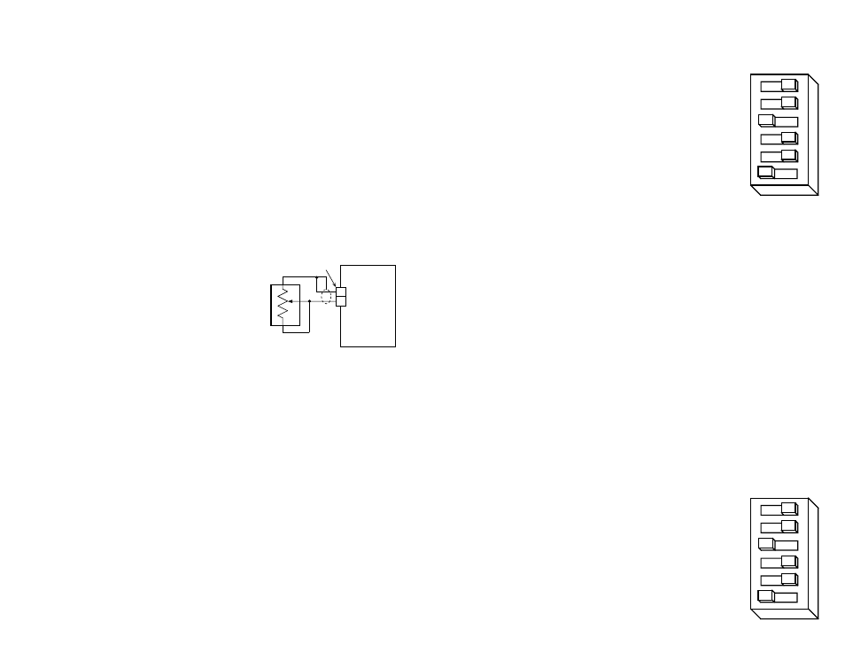
To install the external pot:
• locate the connector on the 3535 O labelled ÒXSPD.Ó It can be found between the
signal connector and the three blue potentiometers.
• turn the screw on the blue SPEED potentiometer 15 turns counterclockwise. If
you don't do this, the external potentiometer will not provide the
correct speed range.
• prepare a cable with your pot on one end and the connector on the other end:
➤ the potentiometer wiper connects to pin 2
➤ the potentiometer CW terminal connects to pin 1
➤ the third pot terminal connects to the wiper
➤ the cable shield connects to the CW pot terminal
With this arrangement, speed will increase as you turn the external pot clockwise.
The frequency range for the 200k
Ω
pot will be
600 to 5000 steps per second.
The frequency range for the 100k
Ω
pot will be
900 to 5000 steps per second.
The on board trimpots will still control
acceleration and declerations times. Turning
the pots clockwise makes the acceleration and
deceleration faster (i.e. reduces the time to or from speed).
HALF STEP
0.1
0.2
0.4
0.8
1.6
cw
3535 O
Drive
external
pot
XSPD
connector
1
2