Operating conditions, 6 mm, 8 mm – d&b D12 Hardware User Manual
Page 21
The table gives power figures for various types of signal waveforms.
They were measured on a D12 driving a 4 ohm load (both channels) to
the clipping point of both channels using a sine wave burst signal of
24 dBu with a variable duty cycle. The mains power supply used for the
measurements supplied an ideal sine wave with 230 V/50 – 60 Hz at
an internal resistance of 0.5 ohms (0.12/0.1 ohms for 115/100 V)
equivalent to a mains lead of 20 m (65.6 ft) with a cross section of
1.5 mm
2
(6 mm
2
/ 8 mm
2
for 115/100 V).
Signal
waveform
CF
Duty
P
out
[W]
P
in
[W]
P
loss
[W]
I
in(230V)
[A]
I
in(115V)
[A]
I
in(100V)
[A]
BTU/hr
kCal/hr
Highly
compressed
music*
2.4
1 : 3.3
800
1230
430
9.2
18.4
20.2
1467
370
Music with low
dynamic range
3.5
1 : 7
400
640
240
5.3
10.6
11.2
819
206
Music with
wide dynamic
range
5.0
1 : 14
200
360
160
3.2
6.4
7.0
546
138
Tab. 8: D12 Power balance
Key:
CF: Crest factor, Duty: Duty cycle, P
out
[W]: Max. average output power (sum of both channels), P
in
[W]: Input power (effective power)
P
loss
: Power loss (thermal power), I
in (xxxV)
[A]: Resulting current,
* Maximum practical operation
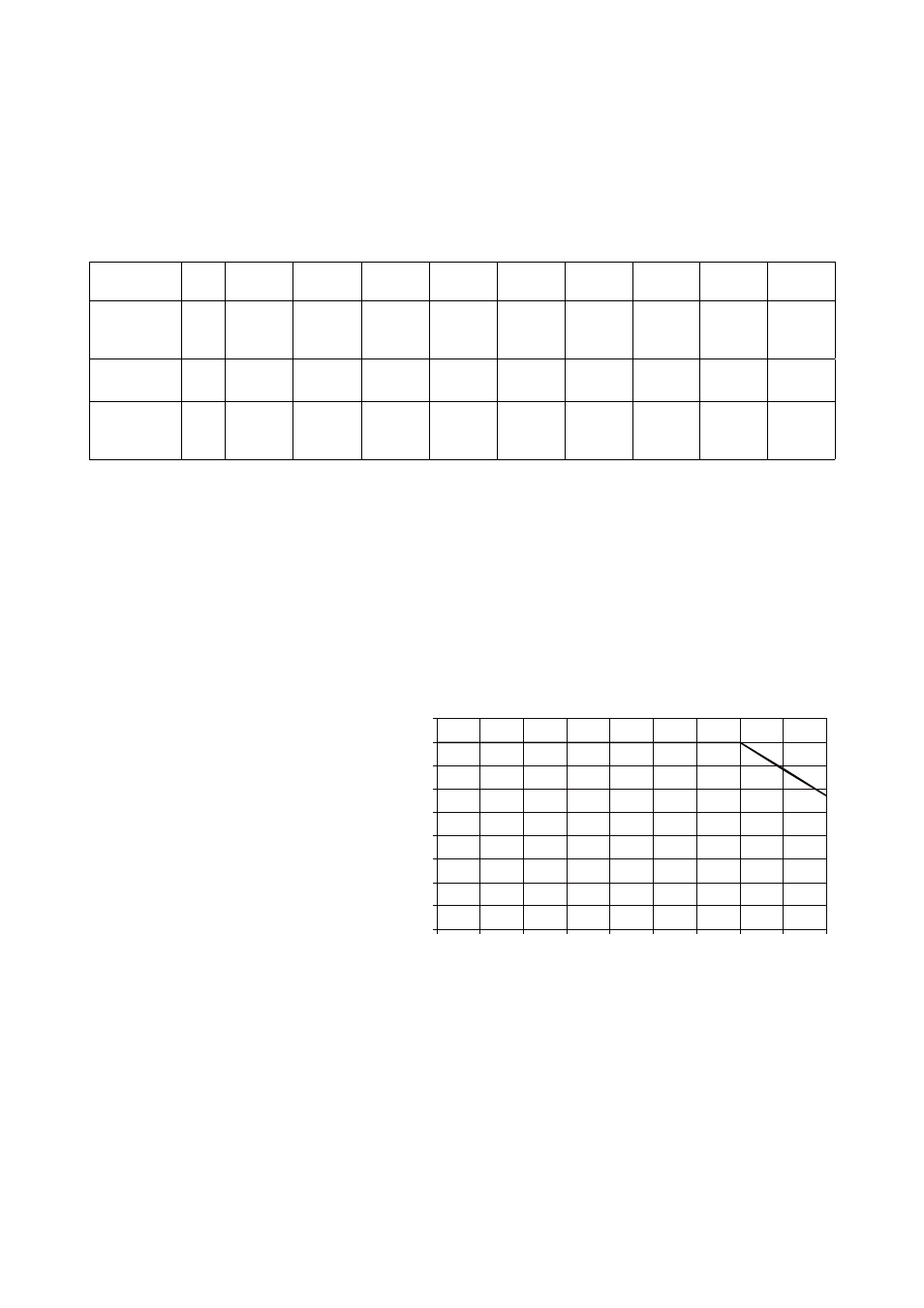
6.2.2. Operating conditions
The following diagram shows the thermal operating range within which
the technical data will be maintained. The operation beyond this range
is possible for a short time and for thermal reasons this will trigger the
amplifier protection circuit into thermal overload.
0
5
10
15
20
25
30
35
40
45
0
100
200
300
400
500
600
700
800
900
Ambient Temp. in °C
M
a
x.
a
ve
ra
g
e
o
u
tp
u
t
P
o
w
e
r
[W
]
Fig. 22: Average maximum total output power vs. ambient
temperature
As explained in section 6.2.1, a worst case signal with a CF of 2.4 is
producing 1/3 of the rated sine output power or 400 watts at 4 ohms
per channel (800 watts total). The thermal management of the D12 is
designed to deliver this power for an unlimited amount of time within an
ambient temperature of up to 35 °C (95 °F). With higher ambient
temperatures, the maximum average output power that can be
delivered without entering thermal protection, is reducing linearly as
shown in the diagram.
D12 Amplifier, Hardware manual
(4.9 EN)
Page 21 of 28