Step 3 – Datapath RSN870 User Manual
Page 6
6
Step 3
Getting Started
Prior to shipment of the RSN870, the Operating System has been installed and fully updated on each of
the SBC’s, the nVidia graphics card drivers have been installed, the ‘Remote Desktop Connection’ has
been enabled and at least one user has been created with ‘Administrator’ status under which the
Renderstation Software has been installled.
How to Connect Outputs
You should exercise great care when connecting all cables to the connectors.
If the pins are oriented correctly and the connector is pushed on squarely, the use of force is not
required. Poor handling may cause some pins to bend within the plug on the cable and this, in turn will
cause damage to the output socket and in some instances will cause irreparable damage to the Printed
Circuit Board. Such damage is not covered under warranty
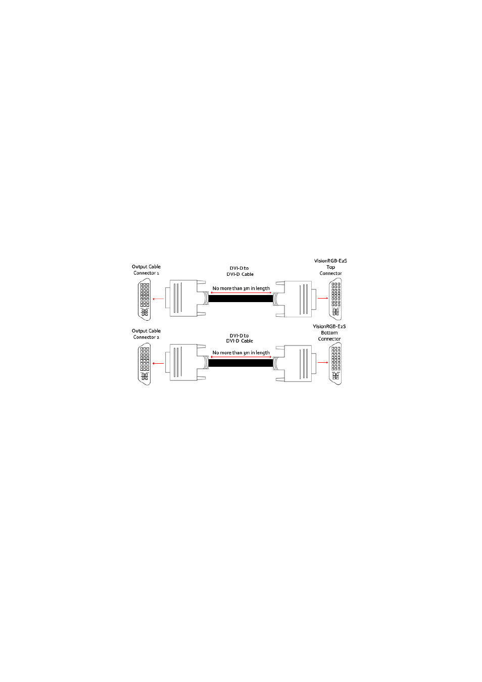
Connect the output splitter cable (
Fig.1
) to the Dual DVI output connector on the nVidia graphics card on
the RSN870 (
Fig.3 -G1/G2/G3
). Using DVI-D cables of no more than 3m in length connect the outputs of
the splitter cable to the inputs of the Vision capture card in the Vision Wall Controller (
Fig. 4
).
Network Connection
The upper network ports (
Fig. 3 - S3
) are pre-configured for communication with the Wall Control software
on the Vision Wall Controller. Using a network cable, connect the upper network ports to the same net-
work as the Vision Wall Controller, this network can also be used to connect to IP cameras.
The lower network port (
Fig. 3 - S4
) is an optional second network port that can be used to provide the
RSN870 with access to a second network for communication with other IP cameras. Only use the second
network port if necessary.
For the process of troubleshooting, the recommended ordering of connection is as follows:
• Connect the outputs from the first nVidia graphics card (
Fig.3 -G1
) to the inputs on the first VisionRGB-
E2S card in the Vision Controller.
• Connect the outputs from the second nVidia graphics card (
Fig.3 -G2
) to the inputs on the second
VisionRGB-E2S card in the Vision Controller.
• Connect the outputs from the third nVidia graphics card (
Fig.3 -G3
) to the inputs on the first
VisionRGB-E2S card in the Vision Controller.
The software will not distinguish the connection ordering, therefore any prefered ordering is acceptable.
Fig.4