Rounding, Arthing, Tatus – KBC Networks ESML6-P3 User Manual
Page 9: 7 grounding / earthing, 8 led status
Ethernet Switch User Manual
Inst_manual_hw-ESML6-P3-Rev_1010A
Copyright © KBC Networks Ltd.
Page 9 of 17
www.kbcnetworks.com
2.7 Grounding / Earthing
The ESML6-P3 has an earth point located on the top panel of the switch. To achieve
the best earth connection, a circular cold-press terminal should be crimped to one
end of the earth wire and attached to the unit with the screw, making sure that the
star washer stays in contact with the body of the switch. The cross-section of
grounding wire should not be less than 2.5mm
2
.
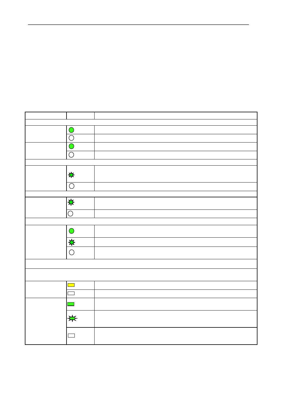
2.8 LED Status
LED
Status
Description
Power
POWER 1
ON
24Vdc power is supplied to POWER 1 input
OFF
No power is supplied to POWER 1 input
POWER 2
ON
24Vdc power is supplied to POWER 2 input
OFF
No power to the unit t POWER 2 input
System Status
RUN1
(left LED)
FLASH
One power supply is lost – the power alarm must be enabled in the web
management
OFF
Power supplies working correctly
System Status
RUN2
(right LED)
FLASH Switch operating normally
OFF
Switch not operating correctly
Gigabit Optical Fiber Ports LED (7,8 & 9)
LINK/ACT
ON
Effective network connection has been established for the port
FLASH Data traffic is passing through the port
OFF
No effective network connection has been established for the port
Ethernet RJ45 Port Status LED (1,2,3,4,5,6)
Each RJ45 Ethernet port has two indicators, a yellow lamp and a green lamp. The yellow lamp indicates
port speed, and the green lamp indicates port link state.
10/100 (Yellow)
ON
100M working status(100Base-TX)
OFF
10M working status(10Base-T)
LINK/ACT
(Green)
ON
Effective network connection has been established for the port
FLASH Data traffic is passing through the port
OFF
No effective network connection has been established for the port