Horizontal suspension – KLING & FREITAG K&F Line 212-9 User Manual
Page 11
User's Manual
LINE 212-6 / LINE 212-9
KLING & FREITAG GMBH ©2003 - 2005
Version 5.0, 23.03.2006
Seite 11 von 37
4.2
Horizontal Suspension
If a speaker unit consisting of several connected systems is to be
flown and aligned, then the individual speakers must be attached
to one another before connecting them to the ‘allsafe JUNGFALK’
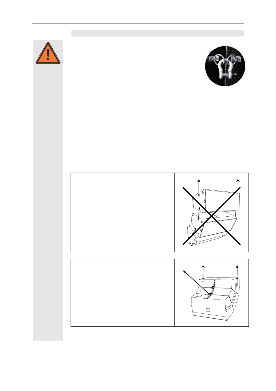
Flying Track. Consult the provided illustration when doing so. For
the rear connection of the loudspeaker systems use the double
stud fittings available from Kling & Freitag and a proven 1/2"
shackle (alternative single stud fittings and 3/8" shackle). Pull the
threaded bolt of the shackle with a torque of 10 Nm (hand-
tight with 200 mm long lever, e.g. screwdriver). Alterna-
tively, you can use proven, high-strength shackles with a
split pin. Only in this way can you ensure that the bolt will not
become loose.
The ‘allsafe JUNGFALK’ Flying Track can only support weights up to 73 kg. Therefore
the load must be distributed on several flying tracks when suspending the systems.
For horizontal operations, the system is designed for a maximum array of 3 Line 212-6
systems. More of theses systems may not be flown below one another.
We recommend using the BGV C1 certified and type tested Click & Fly Rigging System
for mounting the Line 212 systems (see the ‘Click & Fly for Line 212 / SW215E' user's
manual).
Please pay attention to the following instructions for flown operations without
the Click & Fly rigging system:
Wrong:
− The upper rigging points of the top speaker
must carry the full load. Consequently, the
permissible max. load of the top points is ex-
ceeded.
− The speakers are not secured by the additional
safeties
Right:
− The load of the individual speakers is threaded
through the bent continuous bracket. The load
is, therefore, held by the bracket, and the
speakers’ flying points consequently only have
to carry the load of the corresponding speaker.
− The speakers are connected to one another on
the rear. The suspension point is located on the
connection of the two lower speakers. As a re-
sult, the load is distributed to both speakers.
Warning