NEXCOM NEX 732L2G User Manual
Page 20
19
Chapter 2
NEX732L2G User Manual
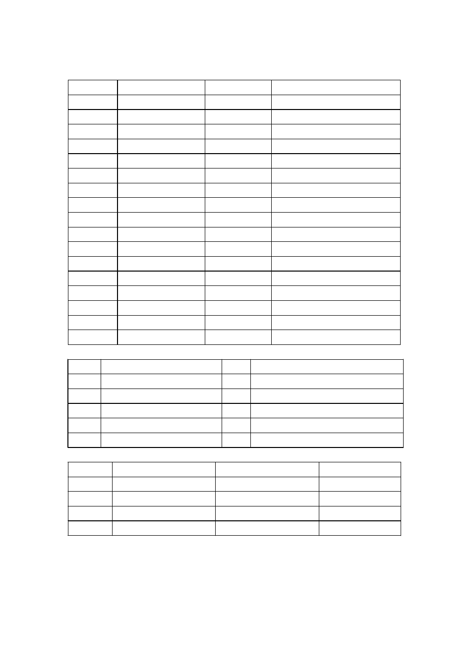
J2 : Floppy Connector
Pin
Definition
Pin
Definition
1
Ground
2
Drive Density Select 0
3 Ground 4 NC
5 Ground 6 NC
7 Ground 8 INDEX#
9 Ground 10 Motor A On#
11 Ground 12 Drive Select B#
13 Ground
14 Drive Select A#
15 Ground
16 Motor B On#
17 Ground 18 Direction of the headstep motor#
19 Ground
20 Step output pulse#
21 Ground
22 Write Data #
23 Ground
24 Write enable#
25 Ground 26 Track 0 #
27 Ground
28 Write Protect #
29 Ground
30 Read Data #
31 Ground 32 Head Select #
33 Ground
34 Diskette change #
J3/J4: COM3/COM4 Connector
Pin
Definition
Pin
Definition
1
Data Carrier Detect (DCD)
2 Serial Input
3 Serial Output
4 Data Terminal Ready (DTR)
5 Chassis Ground 6 Data Set Ready (DSR)
7
Request to send (RTS)
8
Clear to Send (CTS)
9 Ring Indicator (RI) 10 Chassis Ground
J6/J7 : SATA1/ SATA0 Connector
Pin
Definition
Pin
Definition
1 Ground 2 SATA TXP
4 Ground 3 SATA TXN
7 Ground 5 SATA RXN
6
SATA RXP