Xl-h – ThunderMax PN#309-385 - GenII Sportster User Manual
Page 2
www.Thunder-Max.com
309-385 Installation / Setup Guide V2012.06.28
2
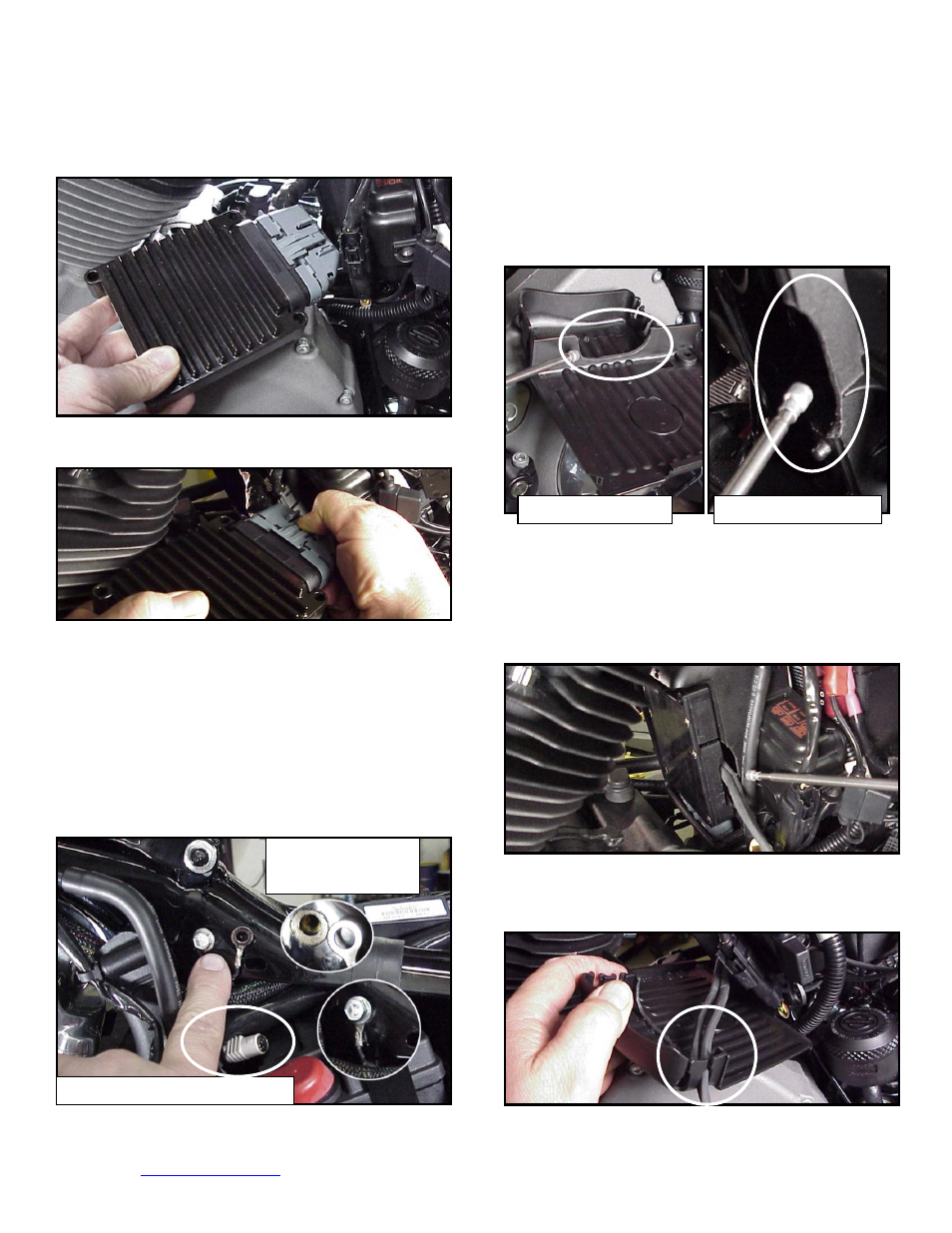
XL-C:
Remove the stock ECM out of the caddy,
towards the primary side of the motorcycle. Lift tang on
the top of the caddy to help release the unit.
XL-D:
Fully depress connector tab and disconnect the
stock ECM from the 36 pin connector
XL-E:
Install ThunderMax Pigtail connector # 309-324
to 36 pin harness connector per connector instructions.
Install ground wire to oil tank mounting bolt on left side of
the frame backbone above the battery as shown.
Carefully scrape paint from frame for a good ground
contact. Run the communication cable straight up inside
the caddy towards the left side of the motorcycle,
between the module area and the frame back bone,
coming out above the battery. Use a wire tie on the
connector to the main harness above the battery for
easy access under left side cover.
XL-F:
With a Dremel® or suitable tool, remove material
from the outer caddy cover to accommodate the
AutoTune wiring as shown; make sure a generous
amount has been removed from this area to avoid
chaffing of the wiring. Grind a relief in the plastic caddy
to match the relief added to the caddy cover, providing
needed clearance for the oxygen sensor wires. The
outer caddy cover will shield the view of this area
XL-G:
C
onnect the pre-dielectric greased ThunderMax
ECM to the greased 36 pin harness plug, ensuring that
the harness plug weather seal does not get pinched
during assembly; firmly press the plug and ECM together
until latched completely. Place the ECM in position with
both sensor wires and AutoTune power cable exiting
through the relief in the ECM caddy as shown.
XL-H:
Insert O
2
wires into cover channels along with
fuel pump wiring connector and reinstall the ECM caddy
cover.
Cover Modification
Housing Modification
Scrape Paint
Before Installation
Communication Port Location