Vectronics VEC-1680K User Manual
Page 10
VEC-1680K Owner’s Manual
Vacuum Tube Preamp
10
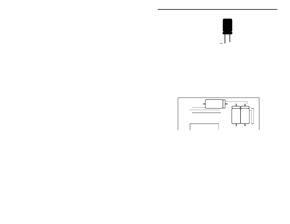
+
Plus Lead
Locate the three (3) 100 uF electrolytic capacitors. Observing polarity:
! ! Install a 100 uF at C4 and solder.
! ! Install a 100 uF at C5 and solder.
! ! Install a 100 uF at C8 and solder.
The remaining three (3) 10 uF, 350 volt, electrolytic capacitors are mounted
laying down flat on the opposite side of the PC board (solder side). Double-
check capacitor polarity--high-voltage capacitors may literally explode with a
"bang" if they're installed backwards!
+
+
_
_
Solder Side
+
_
C6
C1
C2
Flip the PC board over to its solder side and mount the 10 uF caps as shown:
! ! Install a 10 uF at C1 and solder.
! ! Install a 10 uF at C2 and solder.
! ! Install a 10 uF at C6 and solder.
This completes capacitor installation. Before moving on, check each electrolytic
for correct polarity orientation.
While we're working on the solder side, this is a good time to install the two (2)
500K gain-control potentiometers. Locate them now. Before installing, inspect
the type of potentiometer supplied with your kit. If the pins are located on the
front side of the pot, use the front set of mounting holes provided on the PC
board for installation. If the pins are on the rear, use the rear set of mounting