Vectronics VEC-1680K User Manual
Page 14
VEC-1680K Owner’s Manual
Vacuum Tube Preamp
14
! ! Install a spacer in the left-hand mounting hole (do not tighten).
! ! Repeat, installing one in the right-hand mounting hole.
Now, locate the PC board and remove the mounting hardware from the
potentiometers.
Hold the PC board solder-side up with the gain control shafts facing toward you
(the capacitors will be on the right side). Tilting the board toward you, guide the
potentiometer shafts down into their mounting holes--allowing the rear of the PC
board to clear the back lip on the chassis. Drop the PC board into position on its
mounting spacers.
! ! Secure the PC board to its spacers with two 6-32 x ¼” screws.
! ! Tighten all hardware.
! ! Reinstall the potentiometer mounting hardware and tighten.
! ! Bring the ends of the audio and foot-switch leads out from under the
board.
Each of these leads will be installed on the "tip" connection of a ¼” phone jack
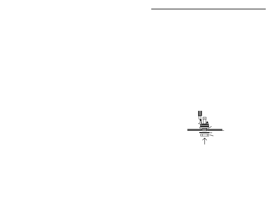
and installed in the chassis. Locate all three (3) ¼” phone jacks and their
hardware--plus the three (3) 9mm spacer washers. Install as outlined below:
Tip
Connection
N.C.
Flat washer
Nut
Spacer washer
! ! Connect the center conductor of the 4" shielded line to the tip connection
on a ¼” jack and solder. Install the jack at Input on the chassis panel.
! ! Connect the center conductor of the 8" shielded line to the tip connection
on a ¼” jack and solder. Install the jack at Output on the chassis panel.
! ! Connect the hook-up wire leading from FOOT to the tip connection on a
¼” jack and solder. Install the jack at Foot Switch on the chassis panel.
Locate the 12.6 volt 1.5-amp power transformer. Also, locate the remaining two
(2) 6-32 x ¼” screws plus the two (2) kep nuts (thin square spring-like nuts).
! ! First cut the white lead off of the transformer. This lead is not needed.