Vectronics VEC-1680K User Manual
Page 13
VEC-1680K Owner’s Manual
Vacuum Tube Preamp
13
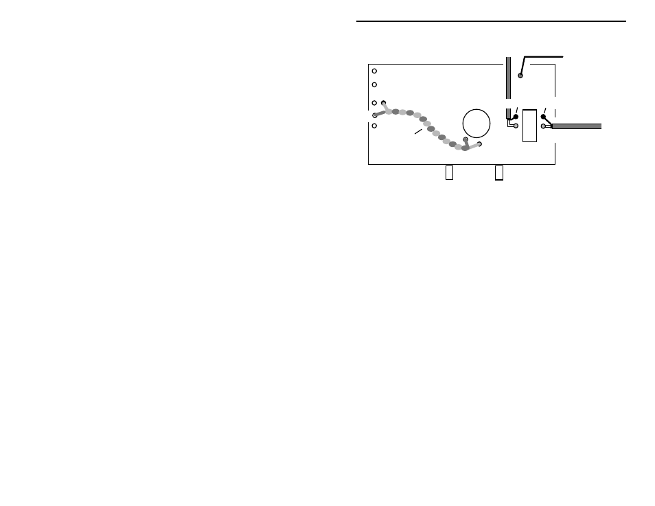
V1
A-1
GNDA-1
GNDA-2
A-2
Input
Output
GND4 GND5
To J1
To J4
To J2
Filament
Line
RLY1
Foot
Input
Output
Footswitch
This completes circuit-board wiring of your VEC- Kit. The remaining point-to-
point wiring will be done with the preamp circuit board mounted in its cabinet.
Before moving on to that phase, give the circuit board a thorough QC (quality
control) inspection. This will help you uncover assembly errors that might
prevent it from working properly. Follow this procedure:
1. Compare parts locations with the parts-placement diagram. Was each part
installed where it is supposed to be? Was the correct value used? Start at
one side of the board and work your way across in an organized pattern.
2. Inspect the solder side of the board for cold-solder joins and solder bridges
between tracks or pads. Use a magnifying glass to obtain a clear view of the
track area. If you suspect a solder bridge, hold the board in front of a bright
light for a better view. All joints should be smooth and shiny, indicating
good solder wetting and flow. Resolder any beaded or dull-appearing
connections.
3. Finally, check electrolytic capacitors and diodes for correct polarity. Does
the plus (+) polarity symbol on the part agree with the pictorial and with the
pattern on the PC board? Is the banded end of each diode positioned
correctly?
Be sure to correct all errors before moving on--once the board is mounted in its
cabinet, further inspections will require disassembly!
Begin final assembly by locating the chassis box and turning it upside down with
the jack and control holes facing you. Looking into the box near the rear wall,
find two mounting holes spaced approximately 4½” apart horizontally. Spacers
will be mounted here to support the PC board. Find two (2) ¾” threaded
aluminum spacers and two (2) 6-32 x ¼” screws.